
 Submit Manuscript
 Peer Review
 Editor Work
- Home
- Articles & Issues
-
Data
- Dataset of Radar Detecting Sea
- SAR Dataset
- SARGroundObjectsTypes
- SARMV3D
- AIRSAT Constellation SAR Land Cover Classification Dataset
- 3DRIED
- UWB-HA4D
- LLS-LFMCWR
- FAIR-CSAR
- MSAR
- SDD-SAR
- FUSAR
- SpaceborneSAR3Dimaging
- Sea-land Segmentation
- SAR Multi-domain Ship Detection Dataset
- SAR-Airport
- Hilly and mountainous farmland time-series SAR and ground quadrat dataset
- SAR images for interference detection and suppression
- HP-SAR Evaluation & Analytical Dataset
- GDHuiYan-ATRNet
- Multi-System Maritime Low Observable Target Dataset
- DatasetinthePaper
- DatasetintheCompetition
- Report
- Course
- About
- Publish
- Editorial Board
- Chinese
| Citation: | LAN Lan, LIAO Guisheng, XU Jingwei, et al. Waveform design and signal processing method of a multifunctional integrated system based on a frequency diverse array[J]. Journal of Radars, 2022, 11(5): 850–870. doi: 10.12000/JR22163

|
Waveform Design and Signal Processing Method of a Multifunctional Integrated System Based on a Frequency Diverse Array(in English)
DOI: 10.12000/JR22163 CSTR: 32380.14.JR22163
More Information-
Abstract
A Frequency Diverse Array (FDA), developed innovatively based on phased array radar, can obtain an angle-range-time-dependent multidimensional transmit beampattern by modulating frequencies across different transmit antenna elements, which considerably increases the beam control ability and signal processing dimension. After joint transmit-receive processing, an FDA can be applied to various areas, such as multidimensional parameter joint estimation, mainlobe deceptive jammer suppression, ambiguous clutter suppression, and high-resolution and wide-swath imaging. This study investigates the waveform design and signal processing method of a multifunctional integrated system based on an FDA from the system level, with emphasis on new signal processing methods for integrated detection and estimation, integrated ambiguity resolution and jammer suppression, as well as integrated Synthetic Aperture Radar (SAR) imaging and moving target detection. Moreover, the application prospects of FDA multifunctional integrated systems are provided. -

-
References
[1] WICKS M C. A brief history of waveform diversity[C]. 2009 IEEE Radar Conference, Pasadena, USA, 2009: 328–333.[2] ANTONIK P, WICKS M C, GRIFFITHS H D, et al. Multi-mission multi-mode waveform diversity[C]. 2006 IEEE Conference on Radar, Verona, USA, 2006: 580–582.[3] 王文钦, 陈慧, 郑植, 等. 频控阵雷达技术及其应用研究进展[J]. 雷达学报, 2018, 7(2): 153–166. doi: 10.12000/JR18029.WANG Wenqin, CHEN Hui, ZHENG Zhi, et al. Advances on frequency diverse array radar and its applications[J]. Journal of Radars, 2018, 7(2): 153–166. doi: 10.12000/JR18029.[4] 许京伟, 朱圣棋, 廖桂生, 等. 频率分集阵雷达技术探讨[J]. 雷达学报, 2018, 7(2): 167–182. doi: 10.12000/JR18023.XU Jingwei, ZHU Shengqi, LIAO Guisheng, et al. An overview of frequency diverse array radar technology[J]. Journal of Radars, 2018, 7(2): 167–182. doi: 10.12000/JR18023.[5] 王文钦, 邵怀宗, 陈慧. 频控阵雷达: 概念、原理与应用[J]. 电子与信息学报, 2016, 38(4): 1000–1011. doi: 10.11999/JEIT151235.WANG Wenqin, SHAO Huaizong, and CHEN Hui. Frequency diverse array radar: Concept, principle and application[J]. Journal of Electronics&Information Technology, 2016, 38(4): 1000–1011. doi: 10.11999/JEIT151235.[6] XU Jingwei, LAN Lan, HE Xiongpeng, et al. System design and signal processing for frequency diverse array radar[J]. Journal of Beijing Institute of Technology, 2021, 30(1): 1–19. doi: 10.15918/j.jbit1004-0579.2021.004.[7] SAMMARTINO P F, BAKER C J, and GRIFFITHS H D. Frequency diverse MIMO techniques for radar[J]. IEEE Transactions on Aerospace and Electronic Systems, 2013, 49(1): 201–222. doi: 10.1109/TAES.2013.6404099.[8] LAN Lan, LIAO Guisheng, XU Jingwei, et al. Control and utilization of range-dependent beampattern with waveform diverse array radars[J]. Chinese Journal of Aeronautics, in press, 2022.[9] XU Jingwei, LIAO Guisheng, ZHU Shengqi, et al. Joint range and angle estimation using MIMO radar with frequency diverse array[J]. IEEE Transactions on Signal Processing, 2015, 63(13): 3396–3410. doi: 10.1109/TSP.2015.2422680.[10] LAN Lan, ROSAMILIA M, AUBRY A, et al. Single-snapshot angle and incremental range estimation for FDA-MIMO radar[J]. IEEE Transactions on Aerospace and Electronic Systems, 2021, 57(6): 3705–3718. doi: 10.1109/TAES.2021.3083591.[11] FENG Maoyuan, CUI Zhongma, YANG Yunxiu, et al. A reduced-dimension MUSIC algorithm for monostatic FDA-MIMO radar[J]. IEEE Communications Letters, 2021, 25(4): 1279–1282. doi: 10.1109/LCOMM.2020.3045440.[12] 刘润东, 薛峰涛, 杨赟秀, 等. FDA-MIMO雷达实值降维求根MUSIC参数估计算法[J]. 现代雷达, 2022, 44(4): 31–37. doi: 10.16592/j.cnki.1004-7859.2022.04.005.LIU Rundong, XUE Fengtao, YANG Yunxiu, et al. Real-value reducing-dimension Root-MUSIC method in monostatic FDA-MIMO radar[J]. Modern Radar, 2022, 44(4): 31–37. doi: 10.16592/j.cnki.1004-7859.2022.04.005.[13] YAN Yisheng, CAI Jingye, and WANG Wenqin. Two-stage ESPRIT for unambiguous angle and range estimation in FDA-MIMO radar[J]. Digital Signal Process, 2019, 92: 151–165. doi: 10.1016/j.dsp.2019.06.002.[14] LI Binbin, BAI Weixiong, and ZHENG Guimei. Successive ESPRIT algorithm for joint DOA-range-polarization estimation with polarization sensitive FDA-MIMO radar[J]. IEEE Access, 2018, 6: 36376–36382. doi: 10.1109/ACCESS.2018.2844948.[15] GONG Shiqi, WANG Shuai, CHEN Sheng, et al. Time-invariant joint transmit and receive beampattern optimization for polarization-subarray based frequency diverse array radar[J]. IEEE Transactions on Signal Processing, 2018, 66(20): 5364–5379. doi: 10.1109/TSP.2018.2868041.[16] XIONG Jie, WANG Wenqin, and GAO Kuandong. FDA-MIMO radar range-angle estimation: CRLB, MSE, and resolution analysis[J]. IEEE Transactions on Aerospace and Electronic Systems, 2018, 54(1): 284–294. doi: 10.1109/TAES.2017.2756498.[17] LI Xingxing, WANG Dangwei, WANG Wenqin, et al. Range-angle localization of targets with planar frequency diverse subaperturing MIMO radar[J]. IEEE Access, 2018, 6: 12505–12517. doi: 10.1109/ACCESS.2018.2810139.[18] 陈慧, 田湘, 李子豪, 等. 共形FDA-MIMO雷达降维目标参数估计研究[J]. 雷达学报, 2021, 10(6): 811–821. doi: 10.12000/JR21197.CHEN Hui, TIAN Xiang, LI Zihao, et al. Reduced-dimension target parameter estimation for conformal FDA-MIMO radar[J]. Journal of Radars, 2021, 10(6): 811–821. doi: 10.12000/JR21197.[19] MAO Zihuan, LIU Shengheng, ZHANG Y D, et al. Joint DOA-range estimation using space-frequency virtual difference coarray[J]. IEEE Transactions on Signal Processing, 2022, 70: 2576–2592. doi: 10.1109/TSP.2022.3173150.[20] TANG Wengen, JIANG Hong, and ZHANG Qi. Range-angle decoupling and estimation for FDA-MIMO radar via atomic norm minimization and accelerated proximal gradient[J]. IEEE Signal Processing Letters, 2020, 27: 366–370. doi: 10.1109/LSP.2020.2972470.[21] 巩朋成, 刘刚, 黄禾, 等. 频控阵MIMO雷达中基于稀疏迭代的多维信息联合估计方法[J]. 雷达学报, 2018, 7(2): 194–201. doi: 10.12000/JR16121.GONG Pengcheng, LIU Gang, HUANG He, et al. Multidimensional parameter estimation method based on sparse iteration in FDA-MIMO radar[J]. Journal of Radars, 2018, 7(2): 194–201. doi: 10.12000/JR16121.[22] ZHU Yu, LIU Lei, LU Zheng, et al. Target detection performance analysis of FDA-MIMO radar[J]. IEEE Access, 2019, 7: 164276–164285. doi: 10.1109/ACCESS.2019.2943082.[23] LI Shengyuan, ZHANG Linrang, LIU Nan, et al. Adaptive detection with conic rejection to suppress deceptive jamming for frequency diverse MIMO radar[J]. Digital Signal Processing, 2017, 69: 32–40. doi: 10.1016/j.dsp.2017.06.008.[24] LI Shengyuan, ZHANG Linrang, LIU Nan, et al. Range-angle dependent detection for FDA-MIMO radar[C]. 2016 IEEE International Geoscience and Remote Sensing Symposium, Beijing, China, 2016: 6629–6632.[25] LAN Lan, MARINO A, AUBRY A, et al. GLRT-based adaptive target detection in FDA-MIMO radar[J]. IEEE Transactions on Aerospace and Electronic Systems, 2021, 57(1): 597–613. doi: 10.1109/TAES.2020.3028485.[26] GUI Ronghua, WANG Wenqin, FARINA A, et al. FDA radar with Doppler-spreading consideration: Mainlobe clutter suppression for blind-Doppler target detection[J]. Signal Processing, 2021, 179: 107773. doi: 10.1016/j.sigpro.2020.107773.[27] XU Ziting, HUANG Bang, and WANG Wenqin. Performance prediction of FDA-MIMO radar detector[C]. 2020 IEEE Radar Conference, Florence, Italy, 2020: 1–6.[28] CHEN Xiaolong, CHEN Baoxin, GUAN Jian, et al. Space-range-Doppler focus-based low-observable moving target detection using frequency diverse array MIMO radar[J]. IEEE Access, 2018, 6: 43892–43904. doi: 10.1109/access.2018.2863745.[29] XU Jingwei, LIAO Guisheng, ZHANG Yuhong, et al. An adaptive range-angle-Doppler processing approach for FDA-MIMO radar using three-dimensional localization[J]. IEEE Journal of Selected Topics in Signal Processing, 2017, 11(2): 309–320. doi: 10.1109/JSTSP.2016.2615269.[30] XU Jingwei, ZHU Shengqi, and LIAO Guisheng. Range ambiguous clutter suppression for airborne FDA-STAP radar[J]. IEEE Journal of Selected Topics in Signal Processing, 2015, 9(8): 1620–1631. doi: 10.1109/JSTSP.2015.2465353.[31] XU Jingwei, LIAO Guisheng, and SO H C. Space-time adaptive processing with vertical frequency diverse array for range-ambiguous clutter suppression[J]. IEEE Transactions on Geoscience and Remote Sensing, 2016, 54(9): 5352–5364. doi: 10.1109/TGRS.2016.2561308.[32] WEN Cai, TAO Mingliang, PENG Jinye, et al. Clutter suppression for airborne FDA-MIMO radar using multi-waveform adaptive processing and auxiliary channel STAP[J]. Signal Processing, 2019, 154: 280–293. doi: 10.1016/j.sigpro.2018.09.016.[33] WEN Cai, MA Changzheng, PENG Jinye, et al. Bistatic FDA-MIMO radar space-time adaptive processing[J]. Signal Processing, 2019, 163: 201–212. doi: 10.1016/j.sigpro.2019.05.025.[34] XU Jingwei, LIAO Guisheng, ZHU Shengqi, et al. Deceptive jamming suppression with frequency diverse MIMO radar[J]. Signal Processing, 2015, 113: 9–17. doi: 10.1016/j.sigpro.2015.01.014.[35] 陈浩, 李荣锋, 戴凌燕, 等. 基于FVE法的FDA-MIMO雷达主瓣密集假目标干扰抑制[J]. 空军预警学院学报, 2018, 32(6): 397–401, 406. doi: 10.3969/j.issn.2095-5839.2018.06.002.CHEN Hao, LI Rongfeng, DAI Lingyan, et al. FDA-MIMO radar mainlobe dense false target jamming suppression based on feature vector eliminating[J]. Journal of Air Force Early Warning Academy, 2018, 32(6): 397–401, 406. doi: 10.3969/j.issn.2095-5839.2018.06.002.[36] 张昭建, 谢军伟, 李欣, 等. 基于FDA-MIMO的距离欺骗干扰鉴别方法[J]. 北京航空航天大学学报, 2017, 43(4): 738–746. doi: 10.13700/j.bh.1001-5965.2016.0257.ZHANG Zhaojian, XIE Junwei, LI Xin, et al. Discrimination method of range deception jamming based on FDA-MIMO[J]. Journal of Beijing University of Aeronautics and Astronautics, 2017, 43(4): 738–746. doi: 10.13700/j.bh.1001-5965.2016.0257.[37] 谭清莉, 张艺乐, 张伟, 等. FDA-MIMO雷达主瓣欺骗干扰对抗方法[J]. 雷达科学与技术, 2017, 15(6): 671–676. doi: 10.3969/j.issn.1672-2337.2017.06.017.TAN Qingli, ZHANG Yile, ZHANG Wei, et al. A method of mainlobe deception jamming countermeasure in FDA-MIMO radar[J]. Radar Science and Technology, 2017, 15(6): 671–676. doi: 10.3969/j.issn.1672-2337.2017.06.017.[38] GE Jiaang, XIE Junwei, and WANG Bo. A cognitive active anti-jamming method based on frequency diverse array radar phase center[J]. Digital Signal Processing, 2021, 109: 102915. doi: 10.1016/j.dsp.2020.102915.[39] 兰岚, 廖桂生, 许京伟, 等. FDA-MIMO雷达主瓣距离欺骗式干扰抑制方法[J]. 系统工程与电子技术, 2018, 40(5): 997–1003. doi: 10.3969/j.issn.1001-506X.2018.05.06.LAN Lan, LIAO Guisheng, XU Jingwei, et al. Main-beam range deceptive jamming suppression approach with FDA-MIMO radar[J]. Systems Engineering and Electronics, 2018, 40(5): 997–1003. doi: 10.3969/j.issn.1001-506X.2018.05.06.[40] 兰岚, 许京伟, 朱圣棋, 等. 波形分集阵列雷达抗干扰进展[J]. 系统工程与电子技术, 2021, 46(6): 1437–1451. doi: 10.12305/j.issn.1001-506X.2021.06.01.LAN Lan, XU Jingwei, ZHU Shengqi, et al. Advances in anti-jamming using waveform diverse array radar[J]. Systems Engineering and Electronics, 2021, 46(6): 1437–1451. doi: 10.12305/j.issn.1001-506X.2021.06.01.[41] LAN Lan, LIAO Guisheng, XU Jingwei, et al. Suppression approach to main-beam deceptive jamming in FDA-MIMO radar using nonhomogeneous sample detection[J]. IEEE Access, 2018, 6: 34582–34597. doi: 10.1109/access.2018.2850816.[42] WANG Yuzhuo and ZHU Shengqi. Main-beam range deceptive jamming suppression with simulated annealing FDA-MIMO radar[J]. IEEE Sensors Journal, 2020, 20(16): 9056–9070. doi: 10.1109/JSEN.2020.2982194.[43] 许京伟, 廖桂生, 张玉洪, 等. 波形分集阵雷达抗欺骗式干扰技术[J]. 电子学报, 2019, 47(3): 545–551. doi: 10.3969/j.issn.0372-2112.2019.03.005.XU Jingwei, LIAO Guisheng, ZHANG Yuhong, et al. On anti-jamming technique with waveform diverse array radar[J]. Acta Electronica Sinica, 2019, 47(3): 545–551. doi: 10.3969/j.issn.0372-2112.2019.03.005.[44] LIU Qi, XU Jingwei, DING Zhi, et al. Target localization with jammer removal using frequency diverse array[J]. IEEE Transactions on Vehicular Technology, 2020, 69(10): 11685–11696. doi: 10.1109/TVT.2020.3016948.[45] LAN Lan, XU Jingwei, LIAO Guisheng, et al. Suppression of mainbeam deceptive jammer with FDA-MIMO radar[J]. IEEE Transactions on Vehicular Technology, 2020, 69(10): 11584–11598. doi: 10.1109/TVT.2020.3014689.[46] LAN Lan, LIAO Guisheng, XU Jingwei, et al. Mainlobe deceptive jammer suppression using element-pulse coding with MIMO radar[J]. Signal Processing, 2021, 182: 107955. doi: 10.1016/j.sigpro.2020.107955.[47] FAROOQ J, TEMPLE M A, and SAVILLE M A. Application of frequency diverse arrays to synthetic aperture radar imaging[C]. 2007 International Conference on Electromagnetics in Advanced Applications, Turin, Italy, 2007: 447–449.[48] FAROOQ J, TEMPLE M A, and SAVILLE M A. Exploiting frequency diverse array processing to improve SAR image resolution[C]. 2008 IEEE Radar Conference, Rome, Italy, 2008: 1–5.[49] WANG Wenqin, SO H C, and SHAO Huaizong. Nonuniform frequency diverse array for range-angle imaging of targets[J]. IEEE Sensors Journal, 2014, 14(8): 2469–2476.[50] WANG Chenghao, XU Jingwei, LIAO Guisheng, et al. A range ambiguity resolution approach for high-resolution and wide-swath SAR imaging using frequency diverse array[J]. IEEE Journal of Selected Topics in Signal Processing, 2017, 11(2): 336–346. doi: 10.1109/JSTSP.2016.2605064.[51] GUO Yifan, LIAO Guisheng, ZHANG Qingjun, et al. A robust radial velocity estimation method for FDA-SAR[J]. IEEE Geoscience and Remote Sensing Letters, 2020, 17(4): 646–650. doi: 10.1109/LGRS.2019.2929493.[52] WANG Hanbing, ZHANG Yuhong, XU Jingwei, et al. A novel range ambiguity resolving approach for high-resolution and wide-swath SAR imaging utilizing space-pulse phase coding[J]. Signal Processing, 2020, 168: 107323. doi: 10.1016/j.sigpro.2019.107323.[53] HE Xiongpeng, LIAO Guisheng, ZHU Shengqi, et al. Range-ambiguous clutter suppression for the SAR-GMTI system based on extended azimuth phase coding[J]. IEEE Transactions on Geoscience and Remote Sensing, 2020, 58(11): 8147–8162. doi: 10.1109/TGRS.2020.2987630.[54] NUSENU S Y, SHAO Huaizong, PAN Ye, et al. Dual-function radar-communication system design via sidelobe manipulation based on FDA butler matrix[J]. IEEE Antennas and Wireless Propagation Letters, 2019, 18(3): 452–456. doi: 10.1109/LAWP.2019.2894015.[55] JI Shilong, CHEN Hui, HU Quan, et al. A dual-function radar-communication system using FDA[C]. 2018 IEEE Radar Conference, Oklahoma, USA, 2018: 23–27.[56] BASIT A, WANG Wenqin, NUSENU S Y, et al. FDA based QSM for mmWave wireless communications: Frequency diverse transmitter and reduced complexity receiver[J]. IEEE Transactions on Wireless Communications, 2021, 20(7): 4571–4584. doi: 10.1109/TWC.2021.3060512.[57] NUSENU S Y and SHAO Huaizong. Green secure communication range-angle focusing quadrature spatial modulation using frequency modulated diverse retrodirective array for mmWave wireless communications[J]. IEEE Transactions on Vehicular Technology, 2019, 68(7): 6867–6877. doi: 10.1109/TVT.2019.2919921.[58] DING Y, ZHANG J, and FUSCO V. Frequency diverse array OFDM transmitter for secure wireless communication[J]. Electronics Letters, 2015, 51(17): 1374–1376. doi: 10.1049/el.2015.1491.[59] GUI Ronghua, ZHENG Zhi, and WANG Wenqin. Cognitive FDA radar transmit power allocation for target tracking in spectrally dense scenario[J]. Signal Processing, 2021, 183: 108006. doi: 10.1016/j.sigpro.2021.108006.[60] SUN Yan, ZHENG Zhi, WANG Wenqin, et al. DOA estimation and tracking for FDA-MIMO radar signal[J]. Digital Signal Processing, 2020, 106: 102858. doi: 10.1016/j.dsp.2020.102858.[61] WANG Yuxi, LI Wei, HUANG Guoce, et al. Time-invariant range-angle-dependent beampattern synthesis for FDA radar targets tracking[J]. IEEE Antennas and Wireless Propagation Letters, 2017, 16: 2375–2379. doi: 10.1109/LAWP.2017.2718580.[62] GUI Ronghua, WANG Wenqin, PAN Ye, et al. Cognitive target tracking via angle-range-Doppler estimation with transmit subaperturing FDA radar[J]. IEEE Journal of Selected Topics in Signal Processing, 2018, 12(1): 76–89. doi: 10.1109/JSTSP.2018.2793761.[63] 巩朋成, 吴云韬. 基于ADMM改进的低截获FDA-MIMO雷达发射波束设计[J]. 通信学报, 2022, 43(4): 133–142. doi: 10.11959/j.issn.1000-436x.2022065.GONG Pengcheng and WU Yuntao. Improved transmit beamforming design based on ADMM for low probability of intercept of FDA-MIMO radar[J]. Journal on Communications, 2022, 43(4): 133–142. doi: 10.11959/j.issn.1000-436x.2022065.[64] WANG Liu, WANG Wenqin, GUAN Haoliang, et al. LPI property of FDA transmitted signal[J]. IEEE Transactions on Aerospace and Electronic Systems, 2021, 57(6): 3905–3915. doi: 10.1109/TAES.2021.3083402.[65] WANG Wenqin, DAI Miaomiao, and ZHENG Zhi. FDA radar ambiguity function characteristics analysis and optimization[J]. IEEE Transactions on Aerospace and Electronic Systems, 2018, 54(3): 1368–1380. doi: 10.1109/TAES.2017.2785598.[66] 于雷, 何峰, 董臻, 等. 一种基于非线性调频信号和空域编码的FDA雷达波形设计方法[J]. 雷达学报, 2021, 10(6): 822–832. doi: 10.12000/JR21008.YU Lei, HE Feng, DONG Zhen, et al. A waveform design method based on nonlinear frequency modulation and space-coding for coherent frequency diverse array radar[J]. Journal of Radars, 2021, 10(6): 822–832. doi: 10.12000/JR21008.[67] FAN Wen, LIANG Junli, and LI Jian. Constant modulus MIMO radar waveform design with minimum peak sidelobe transmit beampattern[J]. IEEE Transactions on Signal Processing, 2018, 66(16): 4207–4222. doi: 10.1109/TSP.2018.2847636.[68] DE MAIO A, DE NICOLA S, HUANG Yongwei, et al. Code design to optimize radar detection performance under accuracy and similarity constraints[J]. IEEE Transactions on Signal Processing, 2008, 56(11): 5618–5629. doi: 10.1109/TSP.2008.929657.[69] YU Xianxiang, CUI Guolong, KONG Lingjiang, et al. Constrained waveform design for colocated MIMO radar with uncertain steering matrices[J]. IEEE Transactions on Aerospace and Electronic Systems, 2019, 55(1): 356–370. doi: 10.1109/TAES.2018.2852200.[70] HE Hao, STOICA P, and LI Jian. Designing unimodular sequence sets with good correlations—Including an application to MIMO radar[J]. IEEE Transactions on Signal Processing, 2009, 57(11): 4391–4405. doi: 10.1109/TSP.2009.2025108.[71] STOICA P, HE Hao, and LI Jian. Optimization of the receive filter and transmit sequence for active sensing[J]. IEEE Transactions on Signal Processing, 2012, 60(4): 1730–1740. doi: 10.1109/TSP.2011.2179652.[72] CUI Guolong, LI Hongbin, and RANGASWAMY M. MIMO radar waveform design with constant modulus and similarity constraints[J]. IEEE Transactions on Signal Processing, 2014, 62(2): 343–353. doi: 10.1109/TSP.2013.2288086.[73] CUI Guolong, YU Xianxiang, CAROTENUTO V, et al. Space-time transmit code and receive filter design for colocated MIMO radar[J]. IEEE Transactions on Signal Processing, 2017, 65(5): 1116–1129. doi: 10.1109/TSP.2016.2633242.[74] HERBERT S, HOPGOOD J R, and MULGREW B. MMSE adaptive waveform design for active sensing with applications to MIMO radar[J]. IEEE Transactions on Signal Processing, 2018, 66(5): 1361–1373. doi: 10.1109/tsp.2017.2786277.[75] MISHRA K V, ELDAR Y C, SHOSHAN E, et al. A cognitive sub-Nyquist MIMO radar prototype[J]. IEEE Transactions on Aerospace and Electronic Systems, 2020, 56(2): 937–955. doi: 10.1109/TAES.2019.2924163.[76] COHEN D, COHEN D, and ELDAR Y C. High resolution FDMA MIMO radar[J]. IEEE Transactions on Aerospace and Electronic Systems, 2020, 56(4): 2806–2822. doi: 10.1109/TAES.2019.2958193.[77] RABASTE O, SAVY L, CATTENOZ M, et al. Signal waveforms and range/angle coupling in coherent colocated MIMO radar[C]. 2013 International Conference on Radar, Adelaide, Australia, 2013: 157–162.[78] 许京伟, 兰岚, 朱圣棋, 等. 相干频率分集阵雷达匹配滤波器设计[J]. 系统工程与电子技术, 2018, 40(8): 1720–1728. doi: 10.3969/j.issn.1001-506X.2018.08.08.XU Jingwei, LAN Lan, ZHU Shengqi, et al. Design of matched filter for coherent FDA radar[J]. Systems Engineering and Electronics, 2018, 40(8): 1720–1728. doi: 10.3969/j.issn.1001-506X.2018.08.08.[79] AUBRY A, DE MAIO A, MARANO S, et al. Single-pulse simultaneous target detection and angle estimation in a multichannel phased array radar[J]. IEEE Transactions on Signal Processing, 2020, 68: 6649–6664. doi: 10.1109/TSP.2020.3039883.[80] XU Jingwei, ZHANG Yuhong, LIAO Guisheng, et al. Resolving range ambiguity via multiple-input multiple-output radar with element-pulse coding[J]. IEEE Transactions on Signal Processing, 2020, 68: 2770–2783. doi: 10.1109/TSP.2020.2988371.[81] 兰岚, 廖桂生, 许京伟, 等. FDA-MIMO雷达非自适应波束形成抗主瓣欺骗式干扰研究[J]. 信号处理, 2019, 35(6): 944–950. doi: 10.16798/j.issn.1003-0530.2019.06.002.LAN Lan, LIAO Guisheng, XU Jingwei, et al. Main-beam deceptive jamming suppression with non-adaptive beam-forming in FDA-MIMO radar[J]. Journal of Signal Processing, 2019, 35(6): 944–950. doi: 10.16798/j.issn.1003-0530.2019.06.002.[82] 朱圣棋, 余昆, 许京伟, 等. 波形分集阵列新体制雷达研究进展与展望[J]. 雷达学报, 2021, 10(6): 795–810. doi: 10.12000/JR21188.ZHU Shengqi, YU Kun, XU Jingwei, et al. Research progress and prospect for the noval waveform diverse array radar[J]. Journal of Radars, 2021, 10(6): 795–810. doi: 10.12000/JR21188.[83] 许京伟. 频率分集阵列雷达运动目标检测方法研究[D]. [博士论文], 西安电子科技大学, 2015.XU Jingwei. Study on moving target detection with frequency diverse array radar[D]. [Ph. D. dissertation], Xidian University, 2015.[84] ZHANG Mengdi, LIAO Guisheng, XU Jingwei, et al. High-resolution and wide-swath SAR imaging with sub-band frequency diverse array[J]. IEEE Transactions on Aerospace and Electronic Systems, in press, 2022.[85] 金林. 智能化认知雷达综述[J]. 现代雷达, 2013, 35(11): 6–11. doi: 10.3969/j.issn.1004-7859.2013.11.002.JIN Lin. Overview of cognitive radar with intelligence[J]. Modern Radar, 2013, 35(11): 6–11. doi: 10.3969/j.issn.1004-7859.2013.11.002.[86] 王晓海. 认知雷达系统技术发展综述[J]. 数字通信世界, 2018(S1): 40–43.WANG Xiaohai. An overview of cognitive radar system technology developments[J]. Digital Communication World, 2018(S1): 40–43. -
Proportional views

- Publishing Ethics
- Journal Insights
- Abstracting & Indexing
- Peer Review Policies
- Guide for Authors
- Conference
- ISSN 2095-283X (Print)ISSN 2097-339X (Online)
- CN 10-1030/TN
- CODEN LXEUAO
About Journal
- Sponsor: China Radio Detection and Ranging Industry Association (CRIA)
- Phone: 010-58887062
- Email:radars@aircas.ac.cn
- Publisher: Leida Xuebao Bianjibu (Editorial office of the Journal of Radars)
Contacts Us

京ICP备20021838号-14
Supported by: Beijing Renhe Information Technology Co. Ltd

Export File
Citation
Format
Content
 DownLoad:


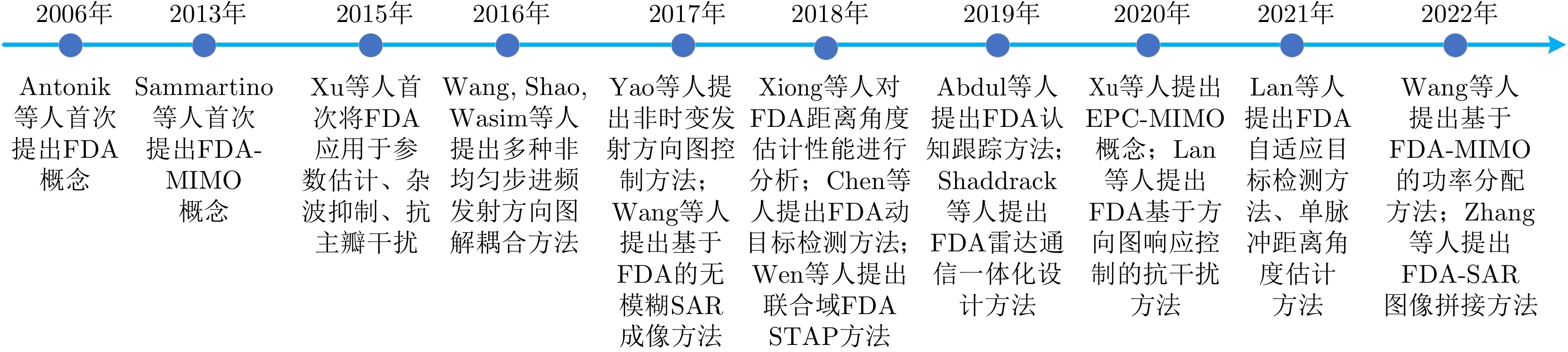
- Figure 1. The dynamic timeline of FDA development
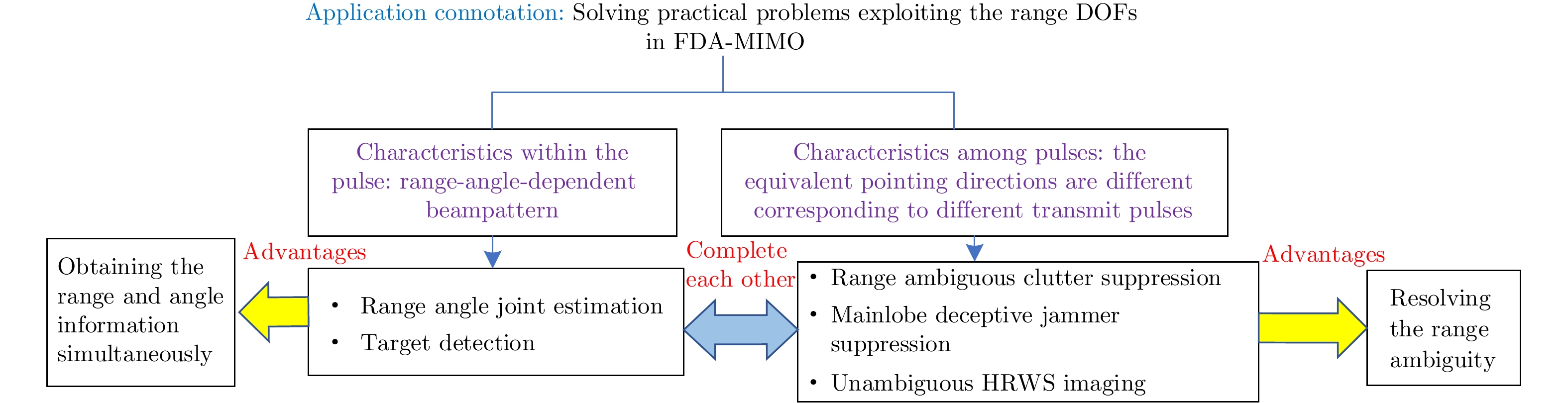
- Figure 2. Relationships among different FDA-MIMO radar applications
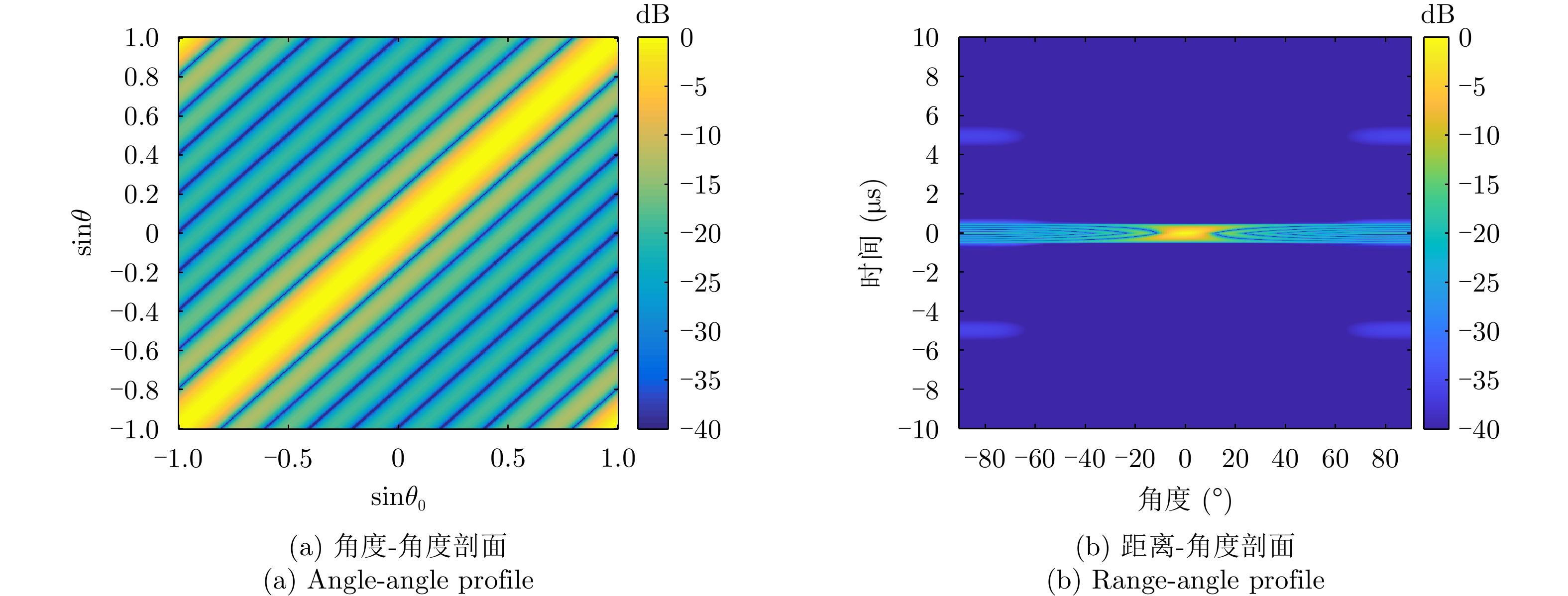
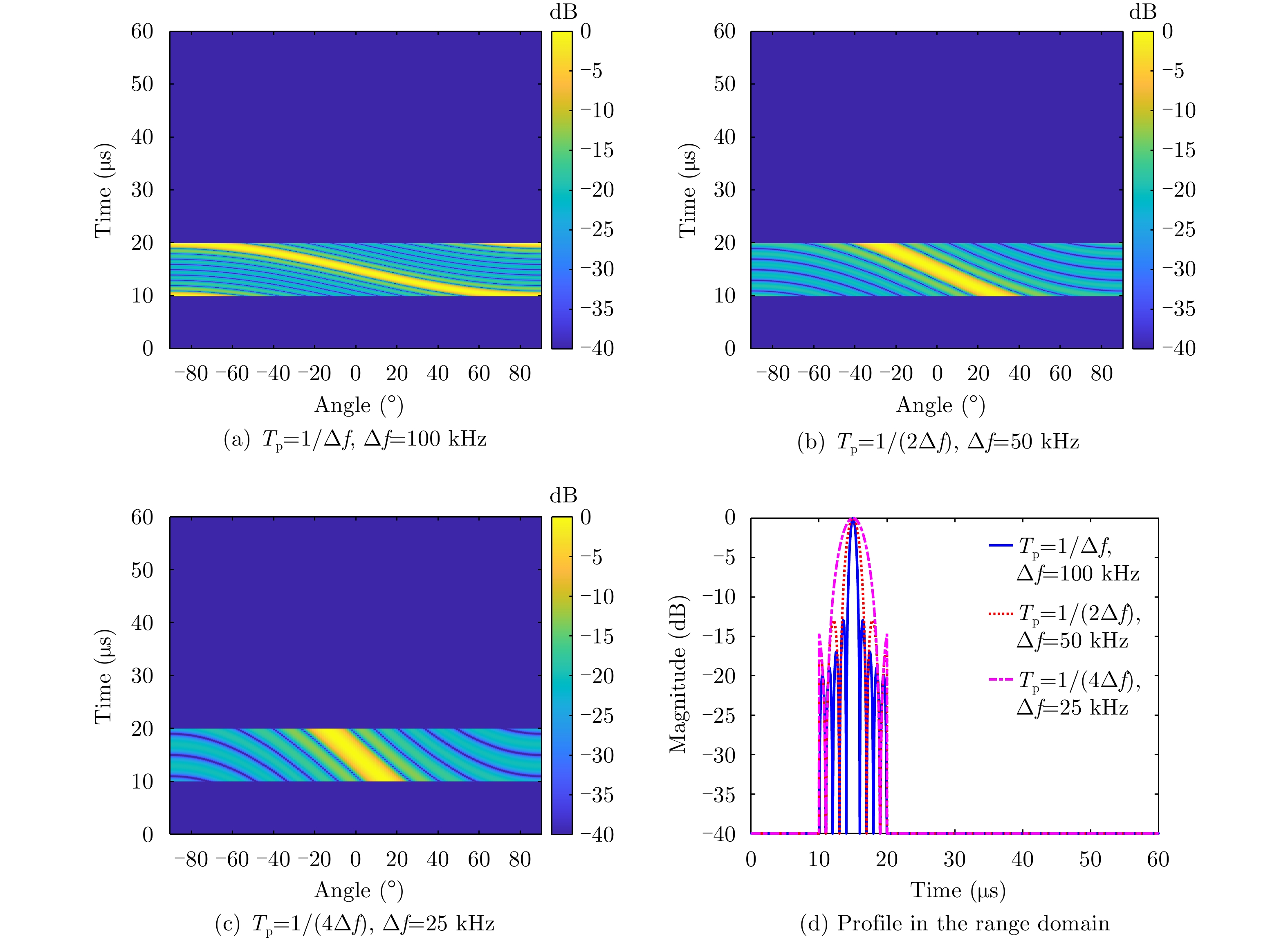
- Figure 3. Multi-dimensional ambiguity function of FDA
- Figure 4. Analysis on the spatial coverage of the transmit beampattern for coherent FDA
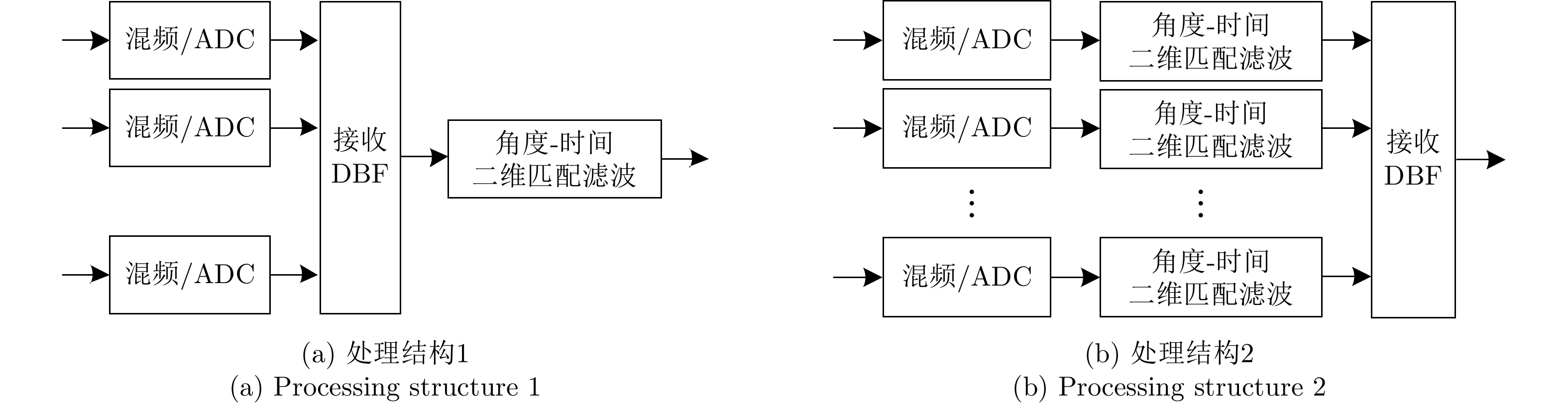
- Figure 5. Basic structures of coherent FDA receiver
- Figure 6. Processing procedurse of receive matched filtering in FDA-MIMO radar
- Figure 7. Integrated detection and estimation results in FDA-MIMO radar
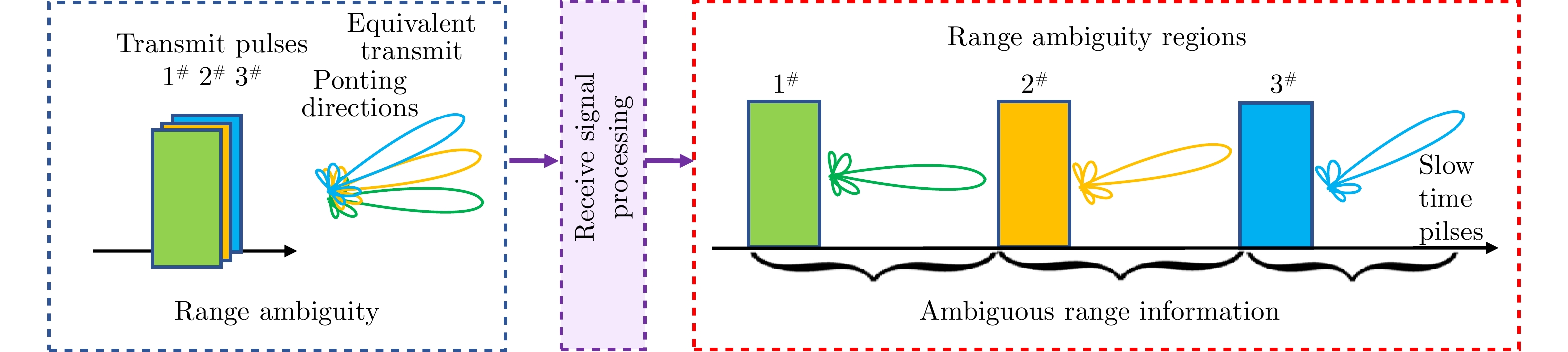
- Figure 8. Principle of resolving the range ambiguity in FDA-MIMO radar
- Figure 9. Generation of false targets
- Figure 10. Mainlobe deceptive jammer suppression with beamforming in FDA-MIMO radar
- Figure 11. Output SINR with robust beamforming for jammer suppression in FDA-MIMO radar
- Figure 12. Verification of jammer suppression with FDA system
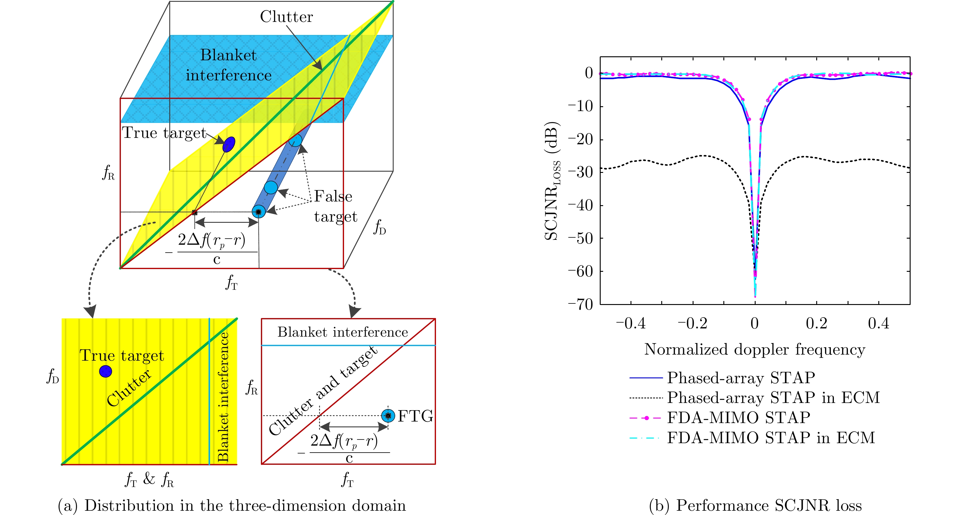
- Figure 13. Integrated clutter and jammer suppression in FDA-MIMO STAP radar
- Figure 14. Signal model of orthogonal frequency diverse LFM signal
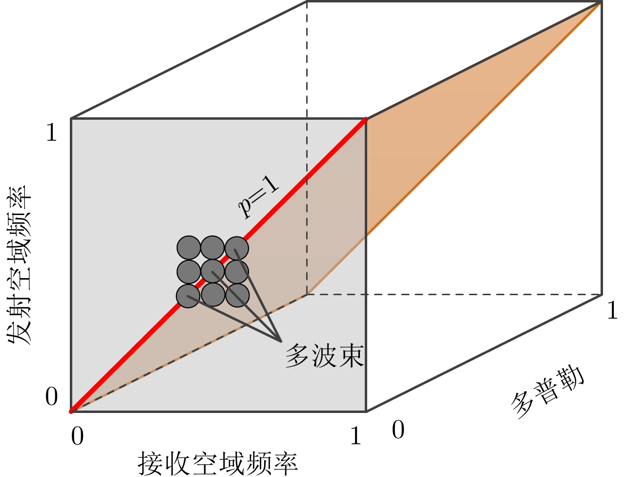
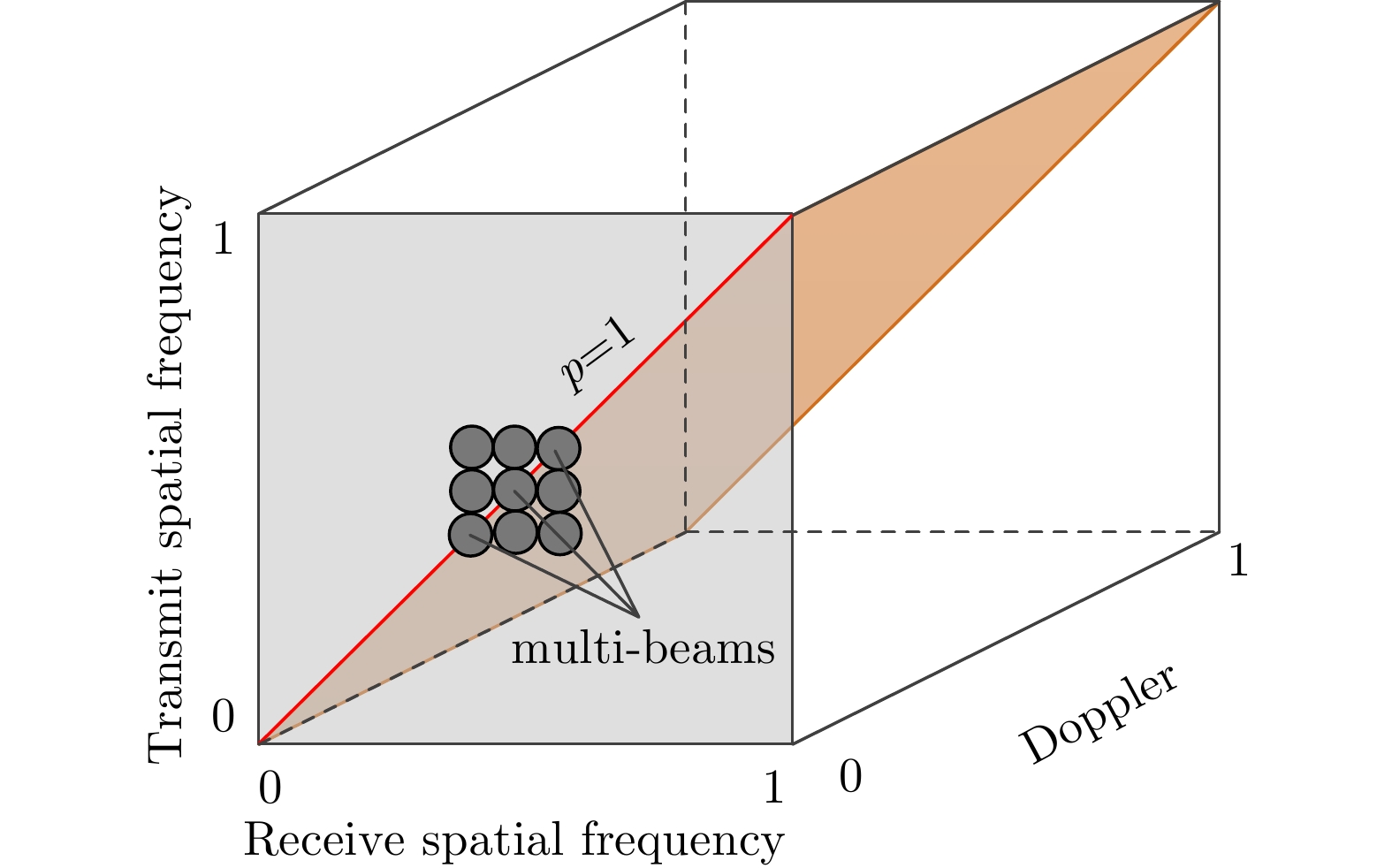
- Figure 15. Diagram of space-time-frequency localized processing with FDA-MIMO
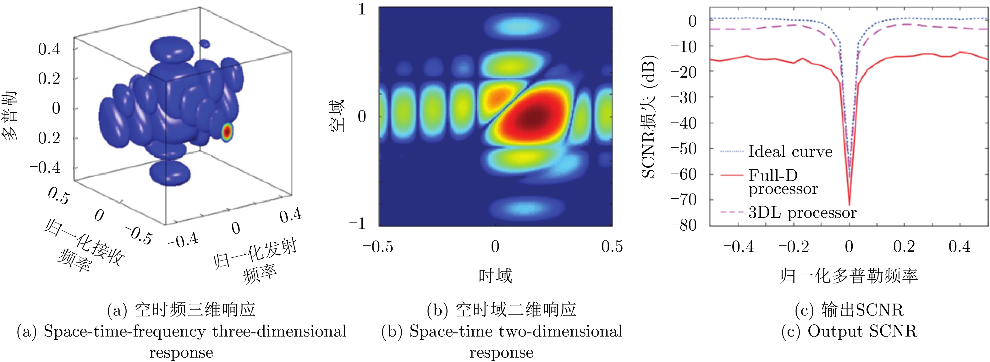
- Figure 16. Results on dimension reduction processor in FDA-MIMO
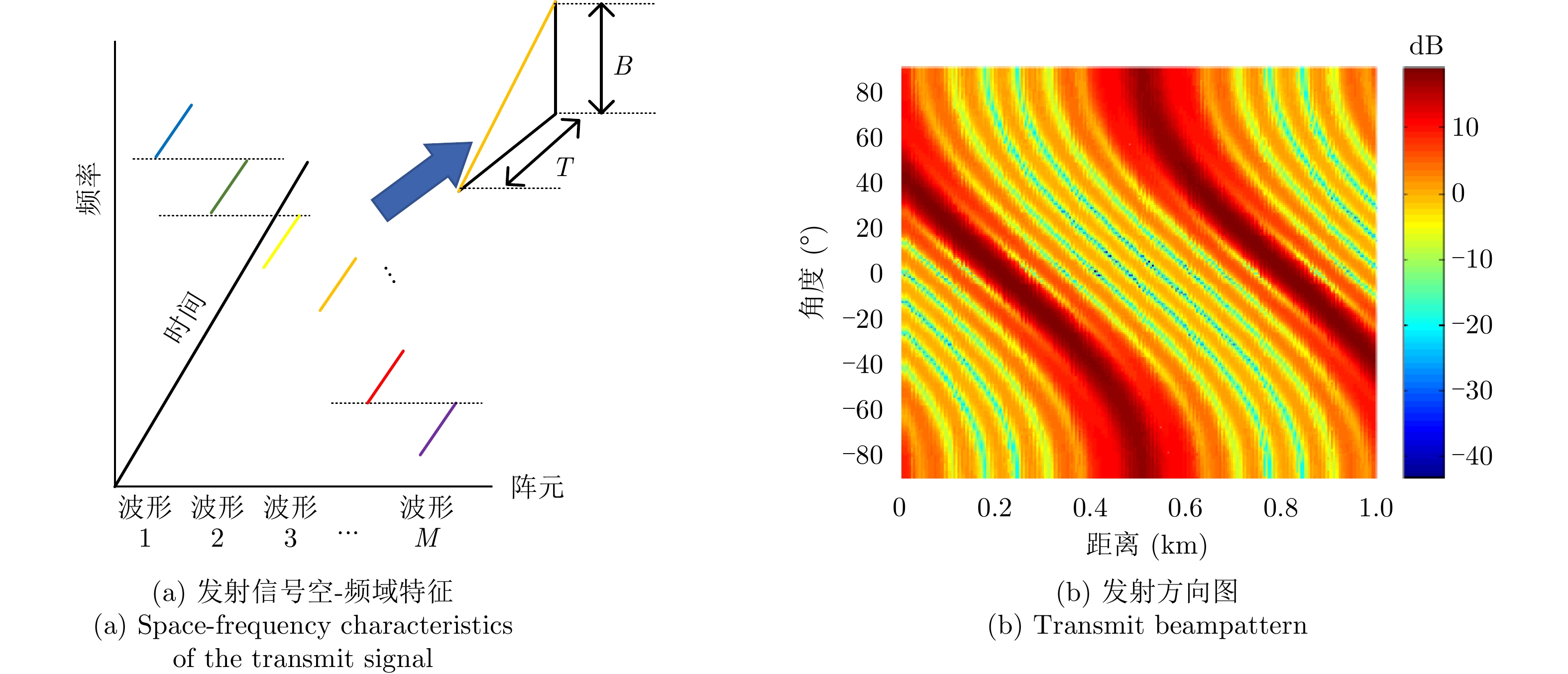
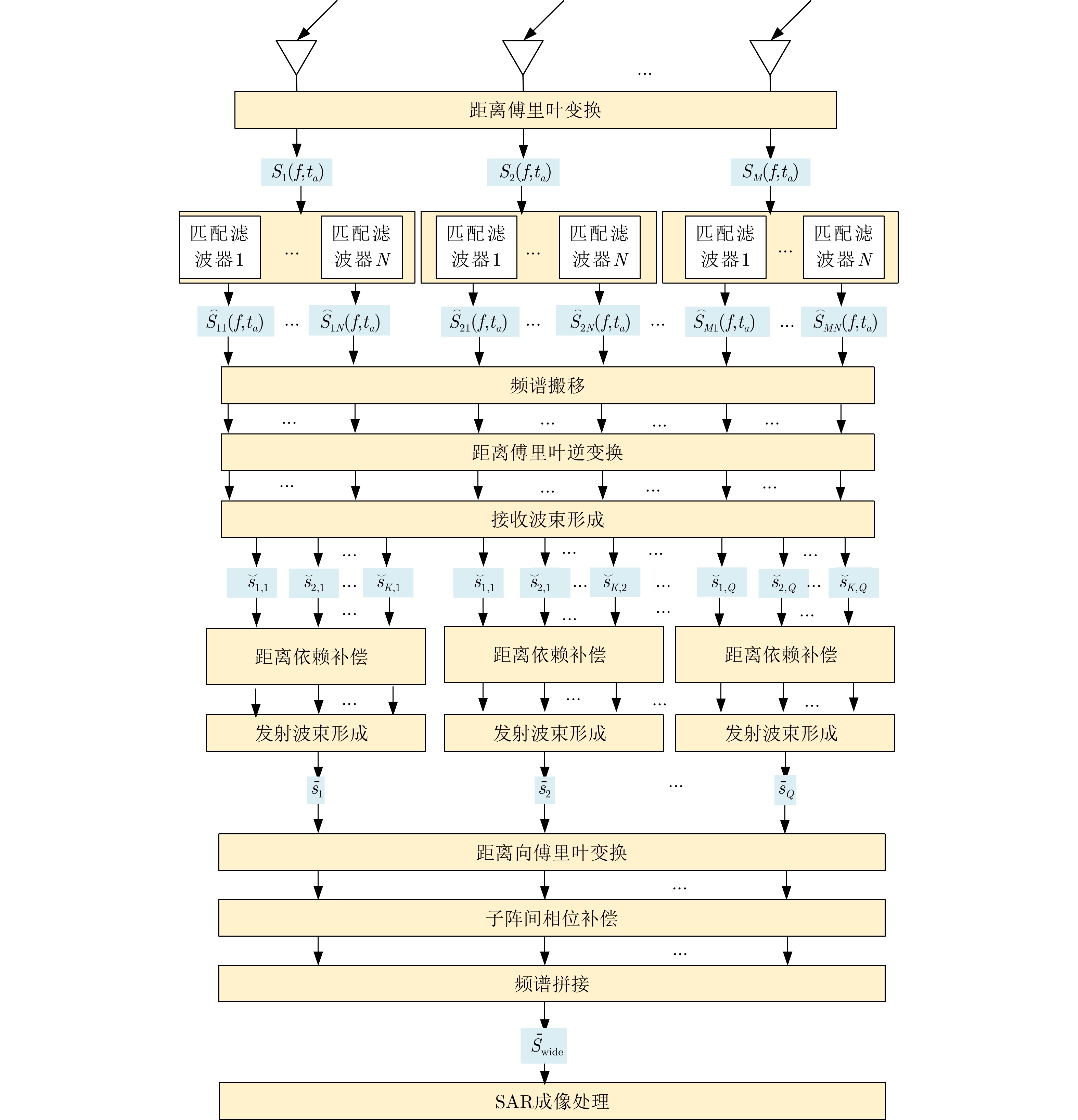
- Figure 17. Procedure of HRWS SAR imaging based on multiple sub-band FDA
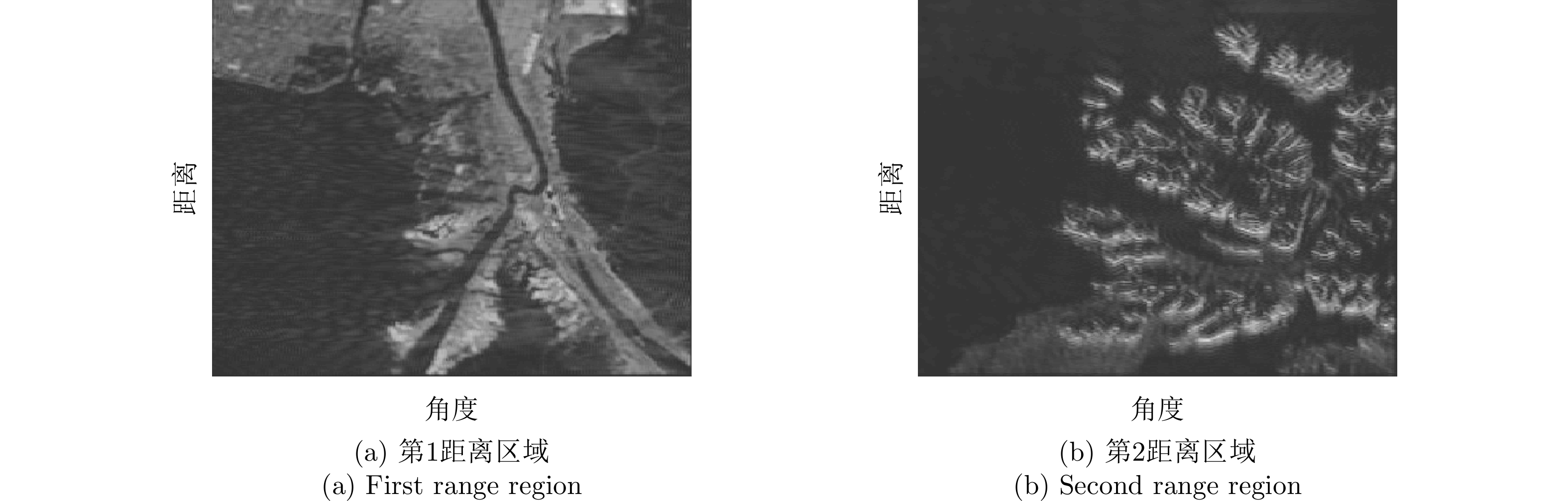
- Figure 18. Imaging results of sub-band FDA-HRWS
- Figure 1.
- Figure 2.
- Figure 3.
- Figure 4.
- Figure 5.
- Figure 6.
- Figure 7.
- Figure 8.
- Figure 9.
- Figure 10.
- Figure 11.
- Figure 12.
- Figure 13.
- Figure 14.
- Figure 15.
- Figure 16.
- Figure 17.
- Figure 18.