Full-polarization SAR Joint Multidimensional Reconstruction Based on Sparse Reconstruction
-
摘要: 各极化通道独立处理和三维分步成像会忽视数据之间的关联性,造成散射中心的失配以及极化散射矩阵获取的不准确。鉴于此,该文提出一种基于稀疏重构的全极化联合多维重建方法。该方法通过设置联合稀疏约束对所有极化通道及所有维度进行联合,将全极化多维重建建模为多通道联合稀疏重构问题。通过数据插值对模型简化后,结合三维快速傅里叶变换、共轭梯度法和牛顿迭代法给出一种高效的模型求解方法,可以同时得到极化散射矩阵和目标三维信息。该文方法保证了不同极化通道、不同维度的稀疏支撑集一致,且充分利用了数据之间的关联性带来的额外信息。基于仿真数据和电磁计算数据的实验结果表明,该方法的性能不受目标类型影响,具有一定的抗噪性,能有效地获取目标的多维重建结果,得到的三维成像结果分辨率高且极化散射矩阵估计精度高。Abstract: Independent processing of each polarization channel and three-dimensional multistage imaging ignore the correlation between data, resulting in the mismatch between scattering centers and the inaccurate acquisition of polarization scattering matrices. To address these issues, a full-polarization Synthetic Aperture Radar (SAR) joint multidimensional reconstruction method based on sparse reconstruction is proposed in this study. In this method, all polarization channels and dimensions are integrated by setting the joint sparse constraints, and the full-polarization SAR joint multidimensional reconstruction is modeled as a multichannel joint sparse reconstruction problem. After the model is simplified by data interpolation, an efficient model-solving method is proposed by combining the three-dimensional fast Fourier transform, conjugate gradient method, and Newton iteration method, where the polarization scattering matrix and three-dimensional information of the target can be obtained at the same time. The proposed method ensures that the sparse support sets of different polarization channels and dimensions are consistent and utilizes the additional information generated by the correlation between data. On the basis of the simulation and electromagnetic calculation data, the experimental results indicate that the proposed method is tolerant of noise and immune to the types of targets. Moreover, the proposed method can effectively obtain the multidimensional reconstruction results of the target, where both the resolution of the imaging results and the estimation accuracy of the polarization scattering matrix are high.
-
表 1 全极化联合多维重建方法的步骤
Table 1. Steps of full polarization joint multi-dimensional reconstruction method
(1) 设定初值:${{\tilde{ \beta }}^n} = {{0}}$; (2) 对每个极化通道, (a) 使用3-D NUFFT对${G_l}(k_x^{},k_y^{},k_z^{})$进行插值,得到
${\hat G_l}(\hat k_x^{},\hat k_y^{},\hat k_z^{})$,(b) 对${\hat G_l}(\hat k_x^{},\hat k_y^{},\hat k_z^{})$进行3-D IFFT,并向量化结果得到
${{\hat{ A}}^{\rm{H}}}{{\hat{ b}}_l}$;(3) 根据所有极化通道的${{\hat{ A}}^{\rm{H}}}{{\hat{ b}}_l}$,得到${{\hat{ A}}^{\rm{H}}}{\hat{ b}}$; (4) 结合3-D FFT,3-D IFFT和共轭梯度法计算
${(2{{\hat{ A}}^{\rm{H}}}{\hat{ A}} + \mu p{{D}}({{\tilde{ \beta }}^n}))^{ - 1}}$;(5) 根据${{\hat{ A}}^{\rm{H}}}{\hat{ b}}$,计算${(2{{\hat{ A}}^{\rm{H}}}{\hat{ A}} + \mu p{{D}}({{\tilde{ \beta }}^n}))^{ - 1}}2{{\hat{ A}}^{\rm{H}}}{\hat{ b}}$; (6) 按式(17)迭代计算${{\tilde{ \beta }}^{n + 1}}$,当${ {\left\| { { { {\tilde{ \beta } } }^{n + 1} } - { { {\tilde{ \beta } } }^n} } \right\|_2^2} \Bigr/ {\left\| { { { {\tilde{ \beta } } }^n} } \right\|_2^2} } < \tau$时
得到解${\tilde{ \beta }} = {{\tilde{ \beta }}^{n + 1}}$;(7) 对${\tilde{ \beta }}$进行Cameron分解,得到全极化联合多维重建结果。 表 2 仿真目标信息
Table 2. Information of simulated targets
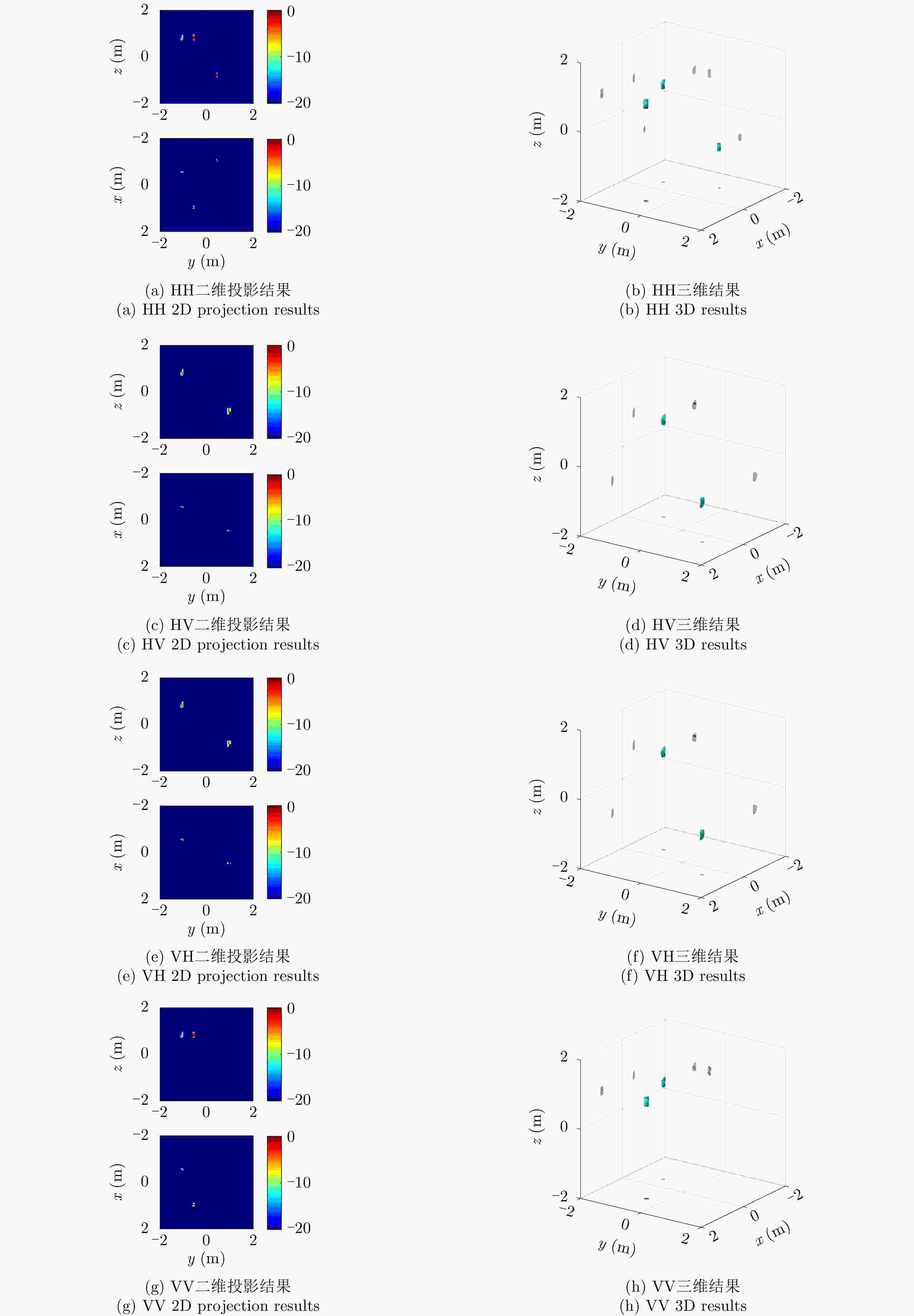
类型 散射矩阵 幅度 位置 三面角 $\left[ {\begin{array}{*{20}{c}} 1&0 \\ 0&1 \end{array}} \right]$ 1 $x = 1.0\,{\rm{m} },y = - 0.5\,{\rm{m} },z = 0.7\,{\rm{m} }$ 偶极子 $\left[ {\begin{array}{*{20}{c}} 1&0 \\ 0&0 \end{array}} \right]$ 1 $x = - 1.0\,{\rm{m} },y = 0.5\,{\rm{m} },z = - 0.7\,{\rm{m} }$ 30°二面角 $\left[ {\begin{array}{*{20}{c}} {0.5}&{0.866} \\ {0.866}&{ - 0.5} \end{array}} \right]$ 1 $x = - 0.5\,{\rm{m} },y = - 1.0\,{\rm{m} },z = 0.7\,{\rm{m} }$ 45°二面角 $\left[ {\begin{array}{*{20}{c}} 0&1 \\ 1&0 \end{array}} \right]$ 1 $x = 0.5\,{\rm{m} },y = 1.0\,{\rm{m} },z = - 0.7\,{\rm{m} }$ 表 3 目标的仿真参数
Table 3. Simulation parameters of simulated targets
雷达扫描参数 值 频率范围 [8 GHz, 12 GHz] 频率采样间隔 20 MHz 方位角范围 [–4°, 6°] 方位角采样间隔 1/14° 俯仰角范围 [18°, 42°] 俯仰角采样间隔 1/14° 极化方式 HH, HV, VH, VV 表 4 仿真目标的极化散射矩阵估计结果
Table 4. Polarization scattering matrix estimation results of simulated targets
方法 目标类型 三面角 偶极子 30°二面角 45°二面角 联合多维重建 变型前 $\left[ {\begin{array}{*{20}{c}} {0.4\operatorname{j} }&0 \\ 0&{0.4{\rm{j}}} \end{array}} \right]$ $\left[ {\begin{array}{*{20}{c}} { - 0.38{\rm{j}}}&0 \\ 0&0 \end{array}} \right]$ $\left[ {\begin{array}{*{20}{c}} { - 0.21}&{ - 0.37} \\ { - 0.37}&{0.21} \end{array}} \right]$ $\left[ {\begin{array}{*{20}{c}} 0&{ - 0.42} \\ { - 0.42}&0 \end{array}} \right]$ 变型后 ${\color{Blue}{0.4} }{ {\rm{e} }^{ {\rm{j} }{ {90}^ \circ } } }{\color{red}{\left[ {\begin{array}{*{20}{c} } 1&0 \\ 0&1 \end{array} } \right] } }$ ${\color{Blue}{0.38} }{ {\rm{e} }^{ {\rm{j} }( - { {90}^ \circ })} }{\color{red}{\left[ {\begin{array}{*{20}{c} } 1&0 \\ 0&0 \end{array} } \right] } }$ ${\color{Blue}{0.42} }{ {\rm{e} }^{ {\rm{j} }{ {180}^ \circ } } }{\color{red}{\left[ {\begin{array}{*{20}{c} } {0.5}&{0.88} \\ {0.88}&{ - 0.5} \end{array} } \right]} }$ ${\color{Blue}{0.42} }{ {\rm{e} }^{ {\rm{j} }{ {180}^ \circ } } }{\color{red}{\left[ {\begin{array}{*{20}{c} } 0&1 \\ 1&0 \end{array} } \right]}}$ 独立多维重建 变型前 $\left[ {\begin{array}{*{20}{c}} {0.38{\rm{j}}}&0 \\ 0&{0.38{\rm{j}}} \end{array}} \right]$ $\left[ {\begin{array}{*{20}{c}} { - 0.38{\rm{j}}}&0 \\ 0&0 \end{array}} \right]$ $\left[ {\begin{array}{*{20}{c}} { - 0.13 + 0.02{\rm{j}}}&{ - 0.34 + 0.06{\rm{j}}} \\ { - 0.34 + 0.06{\rm{j}}}&{0.13 - 0.02{\rm{j}}} \end{array}} \right]$ $\left[ {\begin{array}{*{20}{c}} 0&{ - 0.4 - 0.07{\rm{j}}} \\ { - 0.4 - 0.07{\rm{j}}}&0 \end{array}} \right]$ 变型后 ${\color{Blue}{0.38} }{ {\rm{e} }^{ {\rm{j} }{ {89}^ \circ } } }{\color{red}{\left[ {\begin{array}{*{20}{c} } 1&0 \\ 0&1 \end{array} } \right]}}$ ${\color{Blue}{0.38} }{ {\rm{e} }^{ {\rm{j} }( - { {89}^ \circ })} }{\color{red}{\left[ {\begin{array}{*{20}{c} } 1&0 \\ 0&0 \end{array} } \right]}}$ ${\color{Blue}{0.26} }{ {\rm{e} }^{ {\rm{j} }{ {170}^ \circ } } }{\color{red}{\left[ {\begin{array}{*{20}{c} } {0.5}&{1.35} \\ {1.35}&{ - 0.5} \end{array} } \right]}}$ ${\color{Blue}{0.41} }{ {\rm{e} }^{ {\rm{j} }( - { {170}^ \circ })} }{\color{red}{\left[ {\begin{array}{*{20}{c} } 0&1 \\ 1&0 \end{array} } \right]}}$ 表 5 不同SNR下仿真目标的极化散射矩阵估计结果
Table 5. Polarization scattering matrix estimation results of simulated targets under different SNR
目标类型 SNR=13 dB SNR=18 dB SNR=23 dB 三
面
角变型
前$\left[\!\! {\begin{array}{*{20}{c}} {0.01 + 0.39{\rm{j}}} \!\!\!&\!\!\! {0.02} \\ {0.01 + 0.01{\rm{j}}} \!\!\!&\!\!\! { - 0.02 + 0.39{\rm{j}}} \end{array}} \!\!\right]$ $\left[\!\! {\begin{array}{*{20}{c}} { - 0.02 + 0.4{\rm{j}}} \!\!\!&\!\!\! {0.01 - 0.02{\rm{j}}} \\ {0.03{\rm{j}}} \!\!\!&\!\!\! {0.01 + 0.4{\rm{j}}} \end{array}} \!\!\right]$ $\left[\!\! {\begin{array}{*{20}{c}} {0.01 + 0.41{\rm{j}}} \!\!\!&\!\!\! {0.02{\rm{j}}} \\ { - 0.01} \!\!\!&\!\!\! {0.01 + 0.40{\rm{j}}} \end{array}} \!\!\right]$ 变型
后${\color{blue}{0.39}}{ {\rm{e} }^{ {\rm{j8} }{ {8.7}^ \circ } } }{\color{red}{\left[\!\! {\begin{array}{*{20}{c} } 1 \!\!\!&\!\!\! {0.02 - 0.06{\rm{j} } } \\ {0.03 - 0.04{\rm{j} } } \!\!\!&\!\!\! {1.03 + 0.07{\rm{j} } } \end{array} } \!\!\right]}}$ ${\color{blue}{0.4}}{ {\rm{e} }^{ {\rm{j92} }{\rm{.} }{ {\rm{2} }^{\rm{o} } } }}{\color{red}{\left[\!\! {\begin{array}{*{20}{c} } 1 \!\!\!&\!\!\! { - 0.04 - 0.03{\rm{j} } } \\ {0.09 - 0.01{\rm{j} } } \!\!\!&\!\!\! {1.01 - 0.06{\rm{j} } } \end{array} } \!\!\right] }}$ ${\color{blue}{0.41} }{ {\rm{e} }^{ {\rm{j} }{ {88.6}^ \circ } } }{\color{red}{\left[\!\! {\begin{array}{*{20}{c} } 1 \!\!\!&\!\!\! {0.04} \\ {0.02 + 0.03{\rm{j} } } \!\!\!&\!\!\! {0.97 - 0.01{\rm{j} } } \end{array} } \!\!\right]} }$ 偶
极
子变型
前$\left[\!\! {\begin{array}{*{20}{c}} {0.02 - 0.38{\rm{j}}} \!\!\!&\!\!\! {0.01{\rm{j}}} \\ { - 0.02 + 0.02{\rm{j}}} \!\!\!&\!\!\! { - 0.03{\rm{j}}} \end{array}} \!\!\right]$ $\left[\!\! {\begin{array}{*{20}{c}} {0.02 - 0.41{\rm{j}}} \!\!\!&\!\!\! {0.02 + 0.01{\rm{j}}} \\ { - 0.01 + 0.01{\rm{j}}} \!\!\!&\!\!\! {0.01} \end{array}} \!\!\right]$ $\left[\!\! {\begin{array}{*{20}{c}} { - 0.4{\rm{j}}} \!\!\!&\!\!\! {0.02{\rm{j}}} \\ 0 \!\!\!&\!\!\! 0 \end{array}} \!\!\right]$ 变型
后${\color{blue}{0.3} }{\rm{8} }{ {\rm{e} }^{ {\rm{j( - 86} }{\rm{.} }{ {\rm{8} }^{\rm{o} } }{\rm{)} } } }\!{\color{red}{\left[\!\!\!\! {\begin{array}{*{20}{c} } 1 \!\!\!&\!\!\! { - 0.03} \\ { - 0.05 \!-\! 0.05{\rm{j} } } \!\!\!&\!\!\! {0.08 \!-\! 0.13{\rm{j} } } \end{array} } \!\!\!\right]} }$ $\;{\color{blue}{0.41} }{ {\rm{e} }^{ {\rm{j( - 87} }{\rm{.} }{ {\rm{3} }^{\rm{o} } }{\rm{)} } } }\!{\color{red}{\left[\!\!\!\! {\begin{array}{*{20}{c} } 1 \!\!\!&\!\!\! { - 0.02 \!+\! 0.06{\rm{j} } } \\ { - 0.02 \!-\! 0.01{\rm{j} } } \!\!\!&\!\!\! { - 0.01 \!+\! 0.01{\rm{j} } } \end{array} } \!\!\!\!\right]} }$ ${\color{blue}{0.4} }{ {\rm{e} }^{ {\rm{j - 9} }{ {\rm{0} }^{\rm{o} } } } }{\color{red}{\left[\!\! {\begin{array}{*{20}{c} } 1 \!\!\!&\!\!\! { - 0.05} \\ 0 \!\!\!&\!\!\! 0 \end{array} } \!\!\right]} }$ 30°
二面
角变型
前$\left[\!\! {\begin{array}{*{20}{c}} { - 0.16 + 0.02{\rm{j}}} \!\!\!&\!\!\! { - 0.28 + 0.04{\rm{j}}} \\ { - 0.39 + 0.07{\rm{j}}} \!\!\!&\!\!\! {0.2 - 0.04{\rm{j}}} \end{array}} \!\!\right]$ $\left[\!\! {\begin{array}{*{20}{c}} { - 0.22 + 0.03{\rm{j}}} \!\!\!&\!\!\! { - 0.37 + 0.06{\rm{j}}} \\ { - 0.39 + 0.06{\rm{j}}} \!\!\!&\!\!\! {0.24 - 0.04{\rm{j}}} \end{array}} \!\!\right]$ $\left[\!\! {\begin{array}{*{20}{c}} { - 0.22 + 0.04{\rm{j}}} \!\!\!&\!\!\! { - 0.39 + 0.06{\rm{j}}} \\ { - 0.37 + 0.05{\rm{j}}} \!\!\!&\!\!\! {0.22 - 0.04{\rm{j}}} \end{array}} \!\!\right]$ 变型
后${\color{blue}{0.33} }{ {\rm{e} }^{ {\rm{j172} }{\rm{.} }{ {\rm{4} }^{\rm{o} } } } }{\color{red}{\left[\!\! {\begin{array}{*{20}{c} } {0.5} \!\!\!&\!\!\! {0.84} \\ {1.18 - 0.07{\rm{j} } } \!\!\!&\!\!\! { - 0.6 + 0.04{\rm{j} } } \end{array} } \!\!\right]} }$ ${\color{blue}{0.45} }{ {\rm{e} }^{ {\rm{j172} }{\rm{.} }{ {\rm{3} }^{\rm{o} } } } }{\color{red}{\left[\!\! {\begin{array}{*{20}{c} } {0.5} \!\!\!&\!\!\! {0.85 - 0.03{\rm{j} } } \\ {0.89 - 0.02{\rm{j} } } \!\!\!&\!\!\! { - 0.53 + 0.03{\rm{j} } } \end{array} } \!\!\right]} }$ ${\color{blue}{0.45} }{ {\rm{e} }^{ {\rm{j169} }{\rm{.} }{ {\rm{4} }^{\rm{o} } } } }{\color{red}{\left[\!\! {\begin{array}{*{20}{c} } {0.5} \!\!\!&\!\!\! {0.87 + 0.02{\rm{j} } } \\ {0.84 + 0.04{\rm{j} } } \!\!\!&\!\!\! { - 0.5} \end{array} } \!\!\right]} }$ 45°
二面
角变型
前$\left[\!\! {\begin{array}{*{20}{c}} {0.02} \!\!\!&\!\!\! { - 0.41 - 0.06{\rm{j}}} \\ { - 0.45 - 0.06{\rm{j}}} \!\!\!&\!\!\! { - 0.02} \end{array}} \!\!\right]$ $\left[\!\! {\begin{array}{*{20}{c}} { - 0.01 + 0.01{\rm{j}}} \!\!\!&\!\!\! { - 0.46 - 0.06{\rm{j}}} \\ { - 0.44 - 0.08{\rm{j}}} \!\!\!&\!\!\! { - 0.01{\rm{j}}} \end{array}} \!\!\right]$ $\left[\!\! {\begin{array}{*{20}{c}} 0 \!\!\!&\!\!\! { - 0.43 - 0.01{\rm{j}}} \\ { - 0.42 - 0.08{\rm{j}}} \!\!\!&\!\!\! {0.02{\rm{j}}} \end{array}} \!\!\right]$ 变型
后${\color{blue}{0.42} }{ {\rm{e} }^{ {\rm{j( - 171} }{\rm{.} }{ {\rm{8} }^{\rm{o} } }{\rm{)} } } }{\color{red}{\left[\!\! {\begin{array}{*{20}{c} } { - 0.05} \!\!\!&\!\!\! 1 \\ {1.01} \!\!\!&\!\!\! {0.04} \end{array} } \!\!\right]} }$ ${\color{blue}{0.46} }{ {\rm{e} }^{ {\rm{j( - 172} }{\rm{.} }{ {\rm{4} }^{\rm{o} } }{\rm{)} } } }{\color{red}{\left[\!\! {\begin{array}{*{20}{c} } {0.02 \!-\! 0.01{\rm{j} } } \!\! & \!\! 1 \\ {0.96 \!+\! 0.05{\rm{j} } } \!\! & \!\! {0.01 \!+\! 0.02{\rm{j} } } \end{array} } \!\!\right]} }$ ${\color{blue}{0.44} }{ {\rm{e} }^{ {\rm{j( - 170} }{\rm{.} }{ {\rm{7} }^{\rm{o} } }{\rm{)} } } }{\color{red}{\left[\!\! {\begin{array}{*{20}{c} } 0 \!\!\!&\!\!\! 1 \\ {0.98 \!+\! 0.01{\rm{j} } } \!\!\!&\!\!\! { - 0.02 \!-\! 0.05{\rm{j} } } \end{array} } \!\!\right]} }$ 表 6 Slicy的仿真参数
Table 6. Simulation parameters of Slicy
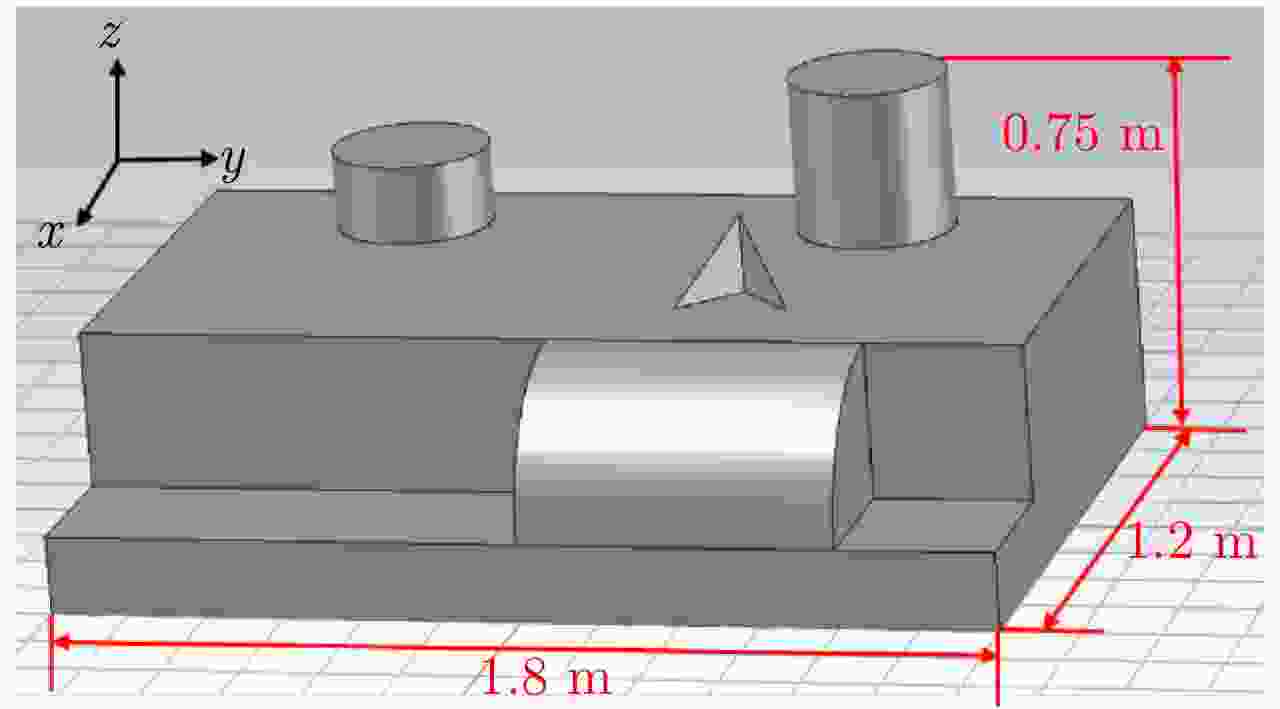
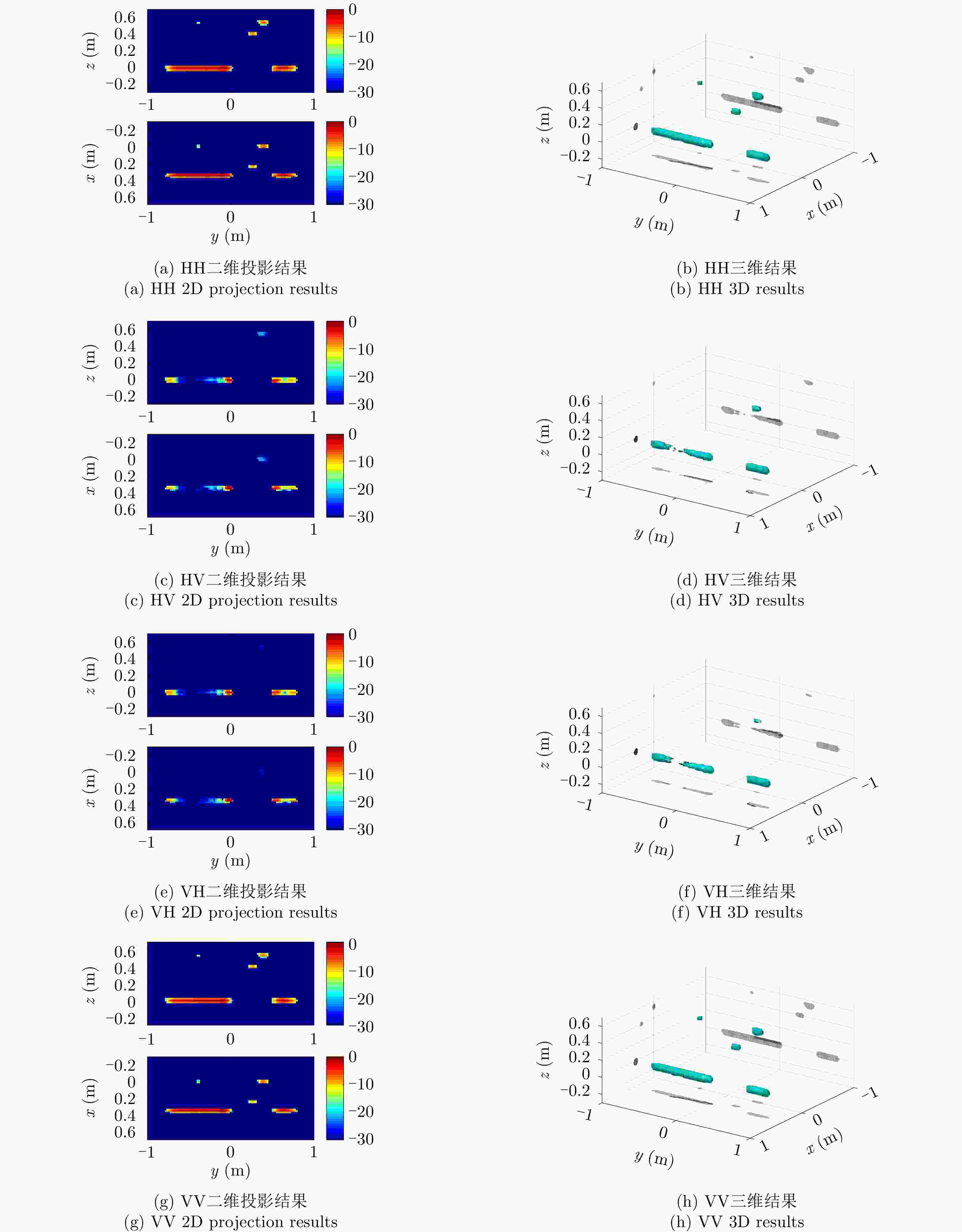
参数类型 参数 取值 雷达扫描参数 频率范围 [8 GHz, 12 GHz] 频率采样间隔 20 MHz 方位角范围 [–4°, 6°] 方位角采样间隔 1/14° 俯仰角范围 [18°, 42°] 俯仰角采样间隔 1/14° 极化方式 HH, HV, VH, VV 场景参数 方位角0° 沿x 轴正方向 俯仰角0° 沿z 轴正方向 x 轴方向场景范围 [–0.6 m, 0.6 m] y 轴方向场景范围 [–0.9 m, 0.9 m] z 轴方向场景范围 [0 m, 0.75 m] 表 7 卫星的仿真参数
Table 7. Simulation parameters of satellite
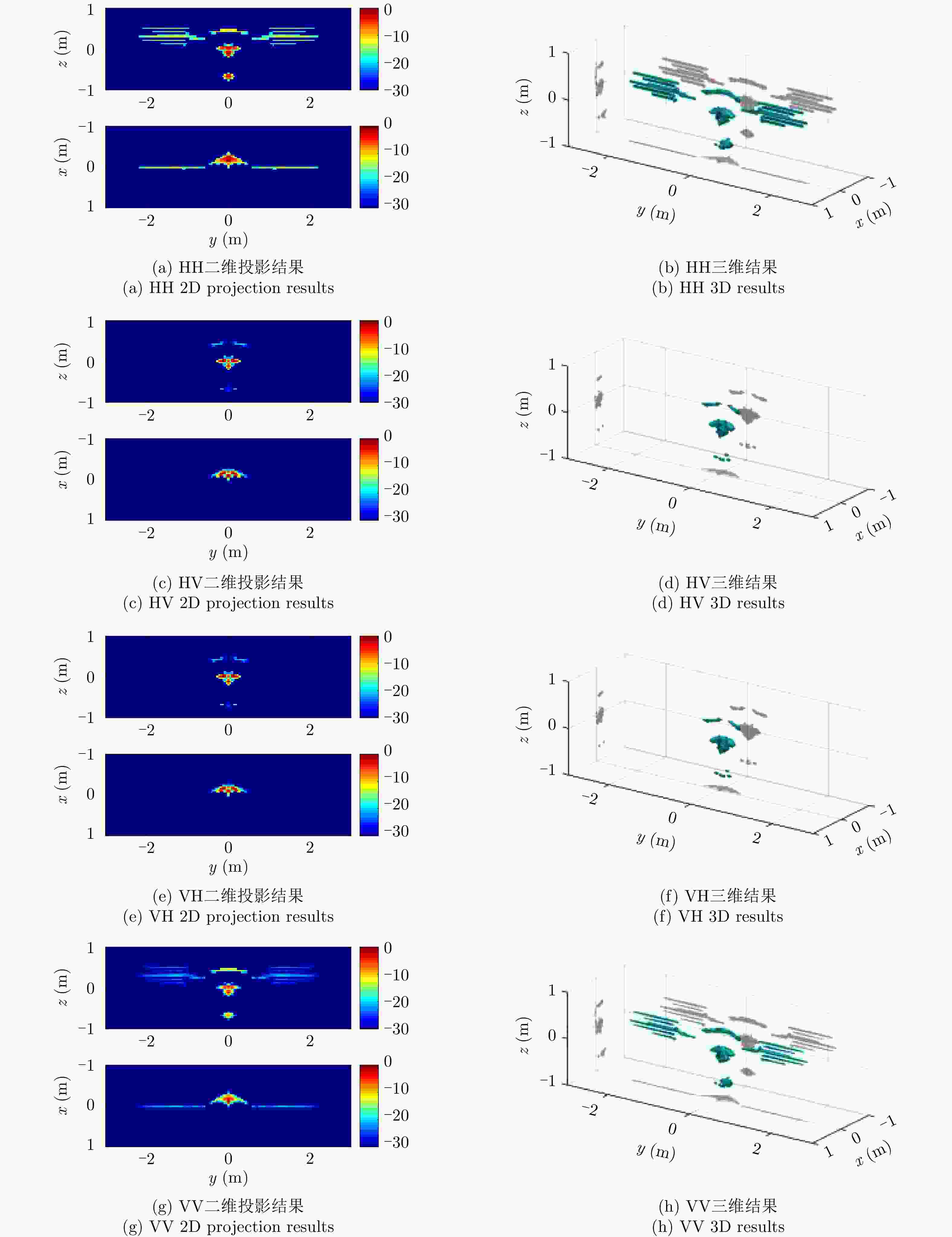
参数类型 参数 取值 雷达扫描参数 频率范围 [9 GHz, 11 GHz] 频率采样间隔 20 MHz 方位角范围 [–20°, 20°] 方位角采样间隔 0.1° 俯仰角范围 [45°, 65°] 俯仰角采样间隔 0.2° 极化方式 HH, HV, VH, VV 场景参数 方位角0° 沿x 轴正方向 俯仰角0° 沿z 轴正方向 x 轴方向场景范围 [–0.5 m, 0.5 m] y 轴方向场景范围 [–4.105 m, 4.105 m] z 轴方向场景范围 [–1.775 m, 1.775 m] -
[1] 保铮, 邢孟道, 王彤. 雷达成像技术[M]. 北京: 电子工业出版社, 2005.BAO Zheng, XING Mengdao, and WANG Tong. Radar Imaging[M] Beijing: Publishing House of Electronics Industry, 2005. [2] CUMMING I G and WONG F H. Digital Processing of Synthetic Aperture Radar Data: Algorithm and Implementation[M]. Boston: Artech House, 2005. [3] LEE J S and POTTIER E. Polarimetric Radar Imaging: From Basics to Applications[M]. Boca Raton, FL: CRC Press, 2009. [4] 庄钊文, 肖顺平, 王雪松. 雷达极化信息处理及其应用[M]. 北京: 国防工业出版社, 1999.ZHUANG Zhaowen, XIAO Shunping, and WANG Xuesong. Radar Polarization Information Processing and Application[M] Beijing: National Defense Industry Press, 1999. [5] FREY O and MEIER E. Analyzing tomographic SAR data of a forest with respect to frequency, polarization, and focusing technique[J]. IEEE Transactions on Geoscience and Remote Sensing, 2011, 49(10): 3648–3659. doi: 10.1109/TGRS.2011.2125972 [6] GUILLASO S, FERRO-FAMIL L, REIGBER A, et al. Building characterization using L-band polarimetric interferometric SAR data[J]. IEEE Geoscience and Remote Sensing Letters, 2005, 2(3): 347–351. doi: 10.1109/LGRS.2005.851543 [7] PONCE O, PRATS-IRAOLA P, SCHEIBER R, et al. First airborne demonstration of holographic SAR tomography with fully polarimetric multicircular acquisitions at L-band[J]. IEEE Transactions on Geoscience and Remote Sensing, 2016, 54(10): 6170–6196. doi: 10.1109/TGRS.2016.2582959 [8] 丁赤飚, 仇晓兰, 吴一戎. 全息合成孔径雷达的概念、体制和方法[J]. 雷达学报, 2020, 9(3): 399–408. doi: 10.12000/JR20063DING Chibiao, QIU Xiaolan, and WU Yirong. Concept, system, and method of holographic synthetic aperture radar[J]. Journal of Radars, 2020, 9(3): 399–408. doi: 10.12000/JR20063 [9] FENG Dong, AN Daoxiang, HUANG Xiaotao, et al. A phase calibration method based on phase gradient autofocus for airborne holographic SAR imaging[J]. IEEE Geoscience and Remote Sensing Letters, 2019, 16(12): 1864–1868. doi: 10.1109/LGRS.2019.2911932 [10] SUN Dou, XING Shiqi, LI Yongzhen, et al. Sub-aperture partitioning method for three-dimensional wide-angle synthetic aperture radar imaging with non-uniform sampling[J]. Electronics, 2019, 8(6): 629. doi: 10.3390/electronics8060629 [11] XING Shiqi, LI Yongzhen, DAI Dahai, et al. Three-dimensional reconstruction of man-made objects using polarimetric tomographic SAR[J]. IEEE Transactions on Geoscience and Remote Sensing, 2013, 51(6): 3694–3705. doi: 10.1109/TGRS.2012.2220145 [12] AUSTIN C D, ERTIN E, and MOSES R L. Sparse signal methods for 3-D radar imaging[J]. IEEE Journal of Selected Topics in Signal Processing, 2011, 5(3): 408–423. doi: 10.1109/JSTSP.2010.2090128 [13] SUN Dou, PANG Bo, XING Shiqi, et al. Direct 3-D sparse imaging using non-uniform samples without data interpolation[J]. Electronics, 2020, 9(2): 321. doi: 10.3390/electronics9020321 [14] ERTIN E, MOSES R L, and POTTER L C. Interferometric methods for three-dimensional target reconstruction with multipass circular SAR[J]. IET Radar, Sonar & Navigation, 2010, 4(3): 464–473. [15] HU Xiaowei, TONG Ningning, GUO Yiduo, et al. MIMO radar 3-D imaging based on multi-dimensional sparse recovery and signal support prior information[J]. IEEE Sensors Journal, 2018, 18(8): 3152–3162. doi: 10.1109/JSEN.2018.2810705 [16] NANNINI M, SCHEIBER R, HORN R, et al. First 3-D reconstructions of targets hidden beneath foliage by means of polarimetric SAR tomography[J]. IEEE Geoscience and Remote Sensing Letters, 2012, 9(1): 60–64. doi: 10.1109/LGRS.2011.2160329 [17] NANNINI M, SCHEIBER R, and HORN R. Imaging of targets beneath foliage with SAR tomography[C]. The 7th European Conference on Synthetic Aperture Radar, Friedrichshafen, Germany, 2008: 1–4. [18] SAUER S, FERRO-FAMIL L, REIGBER A, et al. Three-dimensional imaging and scattering mechanism estimation over urban scenes using dual-baseline polarimetric InSAR observations at L-band[J]. IEEE Transactions on Geoscience and Remote Sensing, 2011, 49(11): 4616–4629. doi: 10.1109/TGRS.2011.2147321 [19] NGUYEN N H, BERRY P, and TRAN H T. Compressive sensing for tomographic imaging of a target with a narrowband bistatic radar[J]. Sensors, 2019, 19(24): 5515. doi: 10.3390/s19245515 [20] ZHU Xiaoxiang and BAMLER R. Super-resolution power and robustness of compressive sensing for spectral estimation with application to spaceborne tomographic SAR[J]. IEEE Transactions on Geoscience and Remote Sensing, 2012, 50(1): 247–258. doi: 10.1109/TGRS.2011.2160183 [21] CETIN M and KARL W C. Feature-enhanced synthetic aperture radar image formation based on nonquadratic regularization[J]. IEEE Transactions on Image Processing, 2001, 10(4): 623–631. doi: 10.1109/83.913596 [22] CAMERON W L and LEUNG L K. Feature motivated polarization scattering matrix decomposition[C]. Proceedings of IEEE International Conference on Radar, Arlington, USA, 1990: 549–557. [23] 阙肖峰, 聂在平, 胡俊. 混合场积分方程结合MLFMA分析导体介质复合目标电磁散射问题[J]. 电子学报, 2007, 35(11): 2062–2066. doi: 10.3321/j.issn:0372-2112.2007.11.006QUE Xiaofeng, NIE Zaiping, and HU Jun. Analysis of EM scattering by composite conducting and dielectric object using combined field integral equation with MLFMA[J]. Acta Electronica Sinica, 2007, 35(11): 2062–2066. doi: 10.3321/j.issn:0372-2112.2007.11.006 -


 作者中心
作者中心 专家审稿
专家审稿 责编办公
责编办公 编辑办公
编辑办公

 下载:
下载:


