Loading [MathJax]/jax/element/mml/optable/BasicLatin.js

基于多输入多输出合成孔径雷达的二维混合基线抗欺骗干扰方法

曾铮 张福博 陈龙永 卜祥玺 周思言

陈慧, 田湘, 李子豪, 等. 共形FDA-MIMO雷达降维目标参数估计研究[J]. 雷达学报, 2021, 10(6): 811–821. DOI: 10.12000/JR21197
引用本文: 曾铮, 张福博, 陈龙永, 等. 基于多输入多输出合成孔径雷达的二维混合基线抗欺骗干扰方法[J]. 雷达学报, 2019, 8(1): 90–99. doi: 10.12000/JR18118
CHEN Hui, TIAN Xiang, LI Zihao, et al. Reduced-dimension target parameter estimation for conformal FDA-MIMO radar[J]. Journal of Radars, 2021, 10(6): 811–821. DOI: 10.12000/JR21197
Citation: ZENG Zheng, ZHANG Fubo, CHEN Longyong, et al. A two-dimensional mixed baseline method based on MIMO-SAR for countering deceptive jamming[J]. Journal of Radars, 2019, 8(1): 90–99. doi: 10.12000/JR18118

基于多输入多输出合成孔径雷达的二维混合基线抗欺骗干扰方法

DOI: 10.12000/JR18118
基金项目: 国家部委基金(41874059)
详细信息
    作者简介:

    曾铮:曾   铮(1994–),男,江西人,北京理工大学学士,中国科学院电子学研究所硕士研究生,主要研究方向为雷达信号处理、合成孔径雷达电子对抗。E-mail: zengzheng16@mails.ucas.ac.cn

    张福博(1988–),男,河北人,博士,中国科学院电子学研究所副研究员,研究方向为多通道SAR 3维重建、新体制雷达、阵列雷达信号处理。E-mail: zhangfubo8866@126.com

    陈龙永(1979–),男,研究员,博士生导师,现任中国科学院电子学研究所微波成像技术重点实验室常务副主任,主要研究方向为高分辨率合成孔径雷达系统、干涉合成孔径雷达系统、微波成像新概念、新体制和新技术等。E-mail: lychen@mail.ie.ac.cn

    卜祥玺(1991–),男,山东人,吉林大学学士,中国科学院电子学研究所博士研究生,主要研究方向为涡旋电磁波的应用、雷达系统设计和雷达成像新技术。E-mail: buxiangxi14@mails.ucas.ac.cn

    周思言(1995–),女,重庆人,中国科学技术大学学士,中国科学院电子学研究所硕士研究生,主要研究方向为雷达信号处理、雷达点云重建。E-mail: zhousiyan17@mails.ucas.ac.cn

    通讯作者:

    陈龙永  lychen@mail.ie.ac.cn

  • 中图分类号: TN958

A Two-dimensional Mixed Baseline Method Based on MIMO-SAR for Countering Deceptive Jamming

Funds: The National Ministries Foundation (41874059)
More Information
  • 摘要: 针对距离延时和方位多普勒频率调制两类合成孔径雷达(SAR)欺骗干扰问题,该文提出一种基于多输入多输出合成孔径雷达(MIMO-SAR)的2维混合基线抗欺骗干扰方法。该方法采用基于MIMO-SAR的相位编码方案,使得多通道信号正交,利用多维相位信息识别欺骗干扰,通过相位补偿抑制干扰目标,从而提升雷达抗欺骗干扰能力。该文采用雷达抗干扰改善因子进行定量效果评估,在平台空间受限的条件下,该文方法比传统单发多收系统的雷达抗干扰改善因子提升3倍。仿真实验结果证明了该方法的有效性与正确性。


  • In recent years, Frequency Diverse Array (FDA) radar has received much attention due to its range-angle-time-dependent beampattern[1,2]. Combining the advantages of FDA and traditional phased array Multiple-Input Multiple-Output (MIMO) radar in the degree of freedom, the FDA Multiple-Input Multiple Output (FDA-MIMO) radar was proposed in Ref. [3] and applied in many fields[4-9]. For parameter estimation algorithm, the authors first proposed a FDA-MIMO target localization algorithm based on sparse reconstruction theory[10], and an unbiased joint range and angle estimation method was proposed in Ref. [11]. The work of Ref. [12] further proved that the FDA-MIMO is superior to traditional MIMO radar in range and angle estimation performance, and the authors of Ref. [13] introduced a super-resolution MUSIC algorithm for target location, and analyzed its resolution threshold. Meanwhile, high-resolution Doppler processing is utilized for moving target parameter estimation[14]. The Estimation of Signal Parameters via Rotational Invariance Technique (ESPRIT) and PARAllel FACtor (PARAFAC) was proposed in Ref. [15], which is a search-free algorithm for FDA-MIMO.

    Moreover, the research of conformal array has received more and more attention. Conformal array is a non-planar array that can be completely attached to the surface of the carrier[16]. It has significant advantages such as reducing the aerodynamic impact on the carrier and smaller radar cross section[17]. In addition, conformal array can achieve wide-angle scanning with a lower SideLobe Level (SLL)[18]. Different from traditional arrays, the element beampattern of conformal array needs to be modeled separately in the parameter estimation due to the difference of carrier curvature[19-21].

    As far as we know, most of the existing researches on FDA-MIMO are based on linear array, while there is little research on the combination of FDA-MIMO and conformal array[22]. In this paper, we replace the receiving array in the traditional FDA-MIMO with conformal array. Compared with conventional FDA-MIMO, conformal FDA-MIMO inherits the merits of conformal array and FDA-MIMO, which can effectively improve the stealth and anti-stealth performance of the carrier, and reduce the volume and the air resistance of the carrier. For conformal FDA-MIMO, we further study the parameters estimation algorithm. The major contributions of this paper are summarized as follows:

    (1) A conformal FDA-MIMO radar model is first formulated.

    (2) The parameter estimation Cramér-Rao Lower Bound (CRLB) for conformal FDA-MIMO radar is derived.

    (3) Inspired by the existing work of Refs. [23,24], a Reduced-Dimension MUSIC (RD-MUSIC) algorithm for conformal FDA-MIMO radar is correspondingly proposed to reduce the complexity.

    The rest of the paper consists of four parts. Section 2 formulates the conformal FDA-MIMO radar model, and Section 3 derives a RD-MUSIC algorithm for conformal FDA-MIMO radar. Simulation results for conformal FDA-MIMO radar with semi conical conformal receiving array are provided in Section 4. Finally, conclusions are drawn in Section 5.

    For the convenience of analysis, we consider a monostatic conformal FDA-MIMO radar which is composed by a M-element linear FDA transmitting array and a N-element conformal receiving array, as shown in Fig. 1. d denotes the inter-element spacing, the carrier frequency at the mth transmitting element is fm=f1+Δf(m1), m=1,2,,M where f1 is the transmission frequency of the first antenna element, which is called as reference frequency, and Δf is the frequency offset between the adjacent array elements.

    Figure  1.  Conformal FDA-MIMO radar

    The complex envelope of the transmitted signal of the mth transmitting element is denoted as φm(t), assume the transmitting waveforms have orthogonality,

    Tpφm(t)φm1(tτ)dt=0,m1m (1)

    where τ denotes the time delay, Tp denotes the pulse duration, and () is conjugate operator. The signal transmitted from the mth element can be expressed as

    sm(t)=am(t,θ,ϕ,r)φm(t),0tTp (2)

    where

    am(t,θ,ϕ,r)=exp{j2π((m1)Δfrcf1(m1)dsinαc(m1)Δft)} (3)

    is the mth element of the transmitting steering vector according to the phase difference between adjacent elements, the angle between far-field target and transmitting array is denoted as α=arcsin(sinθcosϕ), where arcsin() denotes arcsine operator, α can be calculated by using the inner product between the target vector and unit vector along the X-axis. θ,ϕ,r are the elevation, azimuth and range between the target and the origin point, respectively. The phase difference between adjacent elements is

    Δψt0=2π(Δfrcf1dsinαcΔft) (4)

    where c is light speed. For far-field target P(r,θ,ϕ), the transmitting steering vector is

    a0(t,θ,ϕ,r)=[1,exp{jΔψt0},,exp{j(M1)Δψt0}]T (5)

    For the conformal receiving array, as shown in Fig. 1(b), the time delay between target P(r,θ,ϕ) and the nth receiving array element is

    τn=rn/c (6)

    where rn is the range between target and the nth receiving array element. For far-field assumption, the rn can be approximated as

    rnrpnr (7)

    where r denotes the range between the target and the origin point, pn=xnex+yney+znez denotes the position vector from the nth element to origin point, and r=sinθcosϕex+sinθsinϕey+cosθez is the unit vector in target orientation, where ex,ey and ez are the unit vectors along the X- , Y- , and Z-axis, respectively. (xn,yn,zn) are the coordinates of the nth element in the Cartesian coordinate system. For simplicity, we let u=sinθcosϕ, v=sinθcosϕ, so the time delay τn=(r(uxn+vyn+cosθzn))/c. The time delay between the first element and the nth element at the receiving array is expressed as

    Δτrn=τ1τn=u(xnx1)+v(yny1)+cosθ(znz1)c (8)

    And the corresponding phase difference between the first element and the nth element is

    ΔψRn=2πf1Δτrn (9)

    Consequently, the receiving steering vector is

    b(θ,ϕ)=[r1(θ,ϕ),r2(θ,ϕ)exp(jΔψr2),,rN(θ,ϕ)exp(jΔψrN)]T (10)

    where rn(θ,ϕ) is the nth conformal receiving array element beampattern which should be designed in its own local Cartesian coordinate system. In this paper, we utilize Euler rotation method to establish transformation frame between local coordinate system and global coordinate system[25,26].

    Then the total phase difference between adjacent transmitting array elements can be rewritten as

    Δψt=2π(Δf2rcf1dsinαcΔft) (11)

    where the factor 2r in the first term represents the two-way transmission and reception, and the correspondingly transmitting steering vector is written as

    a(t,θ,ϕ,r)=[1,exp{jΔψt},,exp{j(M1)Δψt}]T (12)

    Assuming L far-field targets are located at (θi,ϕi,Ri), i=1,2,,L and snapshot number is K. After matched filtering, the received signal can be formulated as following matrix (13,14)

    X=AS+N (13)

    where the array manifold A is expressed as

    A=[at,r(θ1,ϕ1,r1),,at,r(θL,ϕL,rL)]=[b(θ1,ϕ1)a(θ1,ϕ1,r1),,b(θL,ϕL)a(θL,ϕL,rL)] (14)

    where at,r(θ,ϕ,r) is the joint transmitting-receiving steering vector, S=[s(t1),s(t2),,s(tK)]CL×K and NCMN×K denote the signal matrix and noise matrix, respectively, where noise follows the independent identical distribution, and denotes Kronecker product.

    a(θ,ϕ,r)=[1exp{j2π(2Δfrcf1dsinαc)}exp{j2π(M1)(2Δfrcf1dsinαc)}] (15)

    which can be expressed as

    a(θ,ϕ,r)=a(θ,ϕ)a(r) (16)

    where

    a(r)=[1,exp(j2π2Δfrc),,exp(j2π(M1)2Δfrc)]T (17)
    a(θ,ϕ)=[1,exp(j2πf1dsinαc),,exp[j2π(M1)f1dsinαc]]T (18)

    and represents Hadamard product operator.

    The CRLB can be obtained from the inverse of Fisher information matrix[27,28], which establishes a lower bound for the variance of any unbiased estimator. We employ the CRLB for conformal FDA-MIMO parameter estimation to evaluate the performance of some parameter estimation algorithms.

    The discrete signal model is

    x[k]=at,r(θ,ϕ,r)s[k]+N[k],k=1,2,,K (19)

    For the sake of simplification, we take at,r as the abbreviation of at,r(θ,ϕ,r).

    The Probability Distribution Function (PDF) of the signal model with K snapshots is

    p(x|θ,ϕ,r)=1(2πσ2n)K2exp(1σ2n(xat,rs)H(xat,rs)) (20)

    where x=[x(1),x(2),,x(K)] and s=[s(1),s(2),,s(K)].

    The CRLB matrix form of elevation angle, azimuth angle and range is given by Eq. (21), diagonal elements {Cθθ,Cϕϕ,Crr} represent CRLB of estimating elevation angle, azimuth angle and range, respectively.

    CRLB=[CθθCθϕCθrCϕθCϕϕCϕrCrθCrϕCrr]=FIM1=[F11F12F13F21F22F23F31F32F33] (21)

    The elements of Fisher matrix can be expressed as

    Fij=E[2ln(p(xθ,ϕ,r))xixj],i,j=1,2,3 (22)

    In the case of K snapshots, PDF can be rewritten as

    p(x|θ,ϕ,r)=Cexp{1σ2nKn=1(x[k]at,rs[k])H(x[k]at,rs[k])} (23)

    where C is a constant, natural logarithm of Eq. (23) is

    ln(p(x|θ,ϕ,r))=ln(C)1σ2nKk=1(x[k]at,rs[k])H(x[k]at,rs[k]) (24)

    where ln() represents the logarithm operator. The first entry of Fisher matrix can be expressed as

    F11=E[2ln(p(x|θ,ϕ,r))θ2] (25)

    Correspondingly, the first derivative of natural logarithm is given by

    ln(p(x|θ,ϕ,r))θ=1σ2nKk=1(xH[k]at,rθs[k]aHt,rθs[k]x[k]+aHt,rθat,rs2[n]a+aHt,rat,rθs2[n]) (26)

    Then we can obtain the second derivative of

    2ln(p(x|θ,ϕ,r))θ2=1σ2nKk=1(x[k]H2at,rθ2s[k]2aHt,rθ2s(k)x[k]+2aHt,rθ2at,rs[k]2+aHt,rθat,rθs[k]2+aHt,rθat,rθs[k]2+aHt,r2at,rθ2s[k]2) (27)

    And then we have

    Kk=1x[k]=Kk=1at,rs[k]+N[k]=at,r(θ,ϕ,r)Kk=1s[k] (28)

    and

    Kk=1s2[k]=Kvar(s[k])=Kσ2s (29)

    where var() is a symbol of variance. Therefore, the PDF after quadratic derivation can be written as

    E[2ln(p(x|θ,ϕ,r))θ2]=Kσ2sσ2n(aHt,rθat,rθ+aHt,rθat,rθ)=2Kσ2sσ2nat,rθ2 (30)

    where denotes 2-norm. Similarly, the other elements of the Fisher matrix can also be derived in the similar way, so the Fisher matrix can be expressed as

    CRLB1=FIM=2Kσ2sσ2n[aθ2FIM12FIM13FIM21aϕ2FIM23FIM31FIM32ar2] (31)

    where

    FIM12=12[aHt,rθat,rϕ+aHt,rϕat,rθ],
    FIM13=12[aHt,rθat,rr+aHt,rrat,rθ],
    FIM21=12[aHt,rϕat,rθ+aHt,rθat,rϕ],
    FIM23=12[aHt,rϕat,rr+aHt,rrat,rϕ],
    FIM31=12[aHt,rrat,rθ+aHt,rθat,rr],
    FIM32=12[aHt,rrat,rϕ+aHt,rϕat,rr],
    σ2sσ2n=SNR

    Finally, the CRLB of conformal FDA-MIMO can be calculated by the inverse of Fisher matrix.

    The covariance matrix of the conformal FDA-MIMO receiving signal can be written as

    RX=ARsAH+σ2IMN (32)

    where Rs represents the covariance matrix of transmitting signal, IMN denotes MN dimensional identity matrix. For independent target signal and noise, RX can be decomposed as

    RX=USΛSUHS+UnΛnUHn (33)

    The traditional MUSIC algorithm is utilized to estimate the three-dimensional parameters {θ,ϕ,r}, MUSIC spectrum can be expressed as

    PMUSIC(θ,ϕ,r)=1aHt,r(θ,ϕ,r)UnUHnat,r(θ,ϕ,r) (34)

    The target location can be obtained by mapping the peak indexes of MUSIC spectrum.

    Traditional MUSIC parameter estimation algorithm is realized by 3D parameter search, which has good performance at the cost of high computational complexity. When the angular scan interval is less than 0.1°, the running time of single Monte-Carlo simulation is in hours, which is unpracticable for us to analysis conformal FDA-MIMO estimation performance by hundreds of simulations.

    In order to reduce the computation complexity of the parameter estimation algorithm for conformal FDA-MIMO, we propose a RD-MUSIC algorithm, which has a significant increase in computing speed at the cost of little estimation performance loss.

    At first, we define

    V(θ,ϕ,r)=aHt,r(θ,ϕ,r)HUnUHnat,r(θ,ϕ,r)=[b(θ,ϕ)a(θ,ϕ,r)]HUnUHn[b(θ,ϕ)a(θ,ϕ,r)] (35)

    Eq. (35) can be further calculated by

    V(θ,ϕ,r)=aH(θ,ϕ,r)[b(θ,ϕ)IM]H×UnUHn[b(θ,ϕ)IM]a(θ,ϕ,r)=aH(θ,ϕ,r)Q(θ,ϕ)a(θ,ϕ,r) (36)

    where Q(θ,ϕ)=[b(θ,ϕ)IM]HUnUHn[b(θ,ϕ)IM],

    Eq. (36) can be transformed into a quadratic programming problem. To avoid a(θ,ϕ,r)=0M, we add a constraint eH1a(θ,ϕ,r)=1, where e1 denotes unit vector. As a result, the quadratic programming problem can be redefined as

    {min (37)

    The penalty function can be constructed as

    \begin{split} L(\theta ,\phi ,r) =& {{\boldsymbol{a}}^{\rm{H}}}(\theta ,\phi ,r){\boldsymbol{Q}}(\theta ,\phi ){\boldsymbol{a}}(\theta ,\phi ,r) \\ & - \mu \left({\boldsymbol{e}}_1^{\text{H}}{\boldsymbol{a}}(\theta ,\phi ,r) - 1\right) \\ \end{split} (38)

    where \mu is a constant, because {\boldsymbol{a}}\left( {\theta ,\phi ,r} \right) = {\boldsymbol{a}}\left( {\theta ,\phi } \right) \odot {\boldsymbol{a}}\left( r \right), so we can obtain

    \begin{split} \frac{{\partial L(\theta ,\phi ,r)}}{{\partial {\boldsymbol{a}}(r)}} =& 2{\rm{diag}}\left\{ {{\boldsymbol{a}}(\theta ,\phi )} \right\}{\boldsymbol{Q}}(\theta ,\phi ){\boldsymbol{a}}(\theta ,\phi ,r) \\ & - \mu {\rm{diag}}\left\{ {{\boldsymbol{a}}(\theta ,\phi )} \right\}{\boldsymbol{e}}_{\boldsymbol{1}}^{} \end{split} (39)

    where {\rm{diag}}( \cdot ) denotes diagonalization.

    And then let \dfrac{{\partial L(\theta ,\phi ,r)}}{{\partial {\boldsymbol{a}}(r)}} = 0, we can get

    {\boldsymbol{a}}\left( r \right) = \varsigma {{\boldsymbol{Q}}^{ - 1}}(\theta ,\phi ){\boldsymbol{e}}_1^{}./{\boldsymbol{a}}(\theta ,\phi ) (40)

    where \varsigma is a constant, ./ denotes the division of the corresponding elements, which is opposite of Hadamard product. Substituting the constraint {\boldsymbol{e}}_1^{\rm{H}}{\boldsymbol{a}}(\theta ,\phi ,r) = 1 into {\boldsymbol{a}}\left( r \right) , we can obtain \varsigma = 1/({\boldsymbol{e}}_1^{\rm{H}}{{\boldsymbol{Q}}^{ - 1}} \cdot(\theta ,\phi ){\boldsymbol{e}}_1 ), then {\boldsymbol{a}}\left( r \right) can be expressed as

    {\boldsymbol{a}}\left( r \right) = \frac{{{{\boldsymbol{Q}}^{ - 1}}\left( {\theta ,\phi } \right){{\boldsymbol{e}}_1}}}{{{\boldsymbol{e}}_1^{\rm{H}}{{\boldsymbol{Q}}^{ - 1}}\left( {\theta ,\phi } \right){{\boldsymbol{e}}_1}}}./{\boldsymbol{a}}\left( {\theta ,\phi } \right) (41)

    Substituting {\boldsymbol{a}}\left( r \right) into Eq. (37), the target azimuths and elevations can be estimated by searching two-dimensional azimuth-elevation spectrum,

    \begin{split} \hfill \lt \hat \theta ,\hat \phi \gt =& {\text{arg}}\mathop {\min }\limits_{\theta ,\phi } \frac{1}{{{\boldsymbol{e}}_1^{\text{H}}{{\boldsymbol{Q}}^{ - 1}}(\theta ,\phi ){{\boldsymbol{e}}_{\boldsymbol{1}}}}} \\ =& {\text{arg}}\mathop {\max }\limits_{\theta ,\phi } {\boldsymbol{e}}_1^{\text{H}}{{\boldsymbol{Q}}^{ - 1}}(\theta ,\phi ){{\boldsymbol{e}}_{\boldsymbol{1}}} \end{split} (42)

    Given azimuth-elevation estimations obtained by mapping the L peak points, the range information can be obtained by searching range-dimensional spectrum,

    P\left({\hat \theta _i},{\hat \phi _i},r\right){\text{ }} = \frac{1}{{{\boldsymbol{a}}_{t,r}^{\rm{H}}\left({{\hat \theta }_i},{{\hat \phi }_i},r\right){{\boldsymbol{U}}_n}{\boldsymbol{U}}_n^{\rm{H}}{{\boldsymbol{a}}_{t,r}}\left({{\hat \theta }_i},{{\hat \phi }_i},r\right)}} (43)

    For conformal array, different array layouts produce different element patterns. We select the semi conical conformal array which is shown in Fig. 2 as the receiving array for the following simulation.

    Figure  2.  Conformal FDA-MIMO semi conical receiving array

    The simulation parameters are provided as follows: M = 10,N = 7,{f_1} = 10\;{\rm{GHz}},\Delta f = 3\;{\rm{kHz}}, d = \lambda /2 = c/2{f_1} and c = 3 \times {10^8}\;{\rm{m}}/{\rm{s}}.

    We first analyze the computational complexity of the algorithms in respect of the calculation of covariance matrix, the eigenvalue decomposition of the matrix and the spectral search. The main complexity of the MUISC algorithm and our proposed RD-MUISC algorithm are respectively as

    O\left(KL{({MN})^2} + 4/3{({MN})^{\text{3}}}{{ + L}}{\eta _1}{\eta _2}{\eta _3}{({MN})^2} \right) (44)
    O\left(KL{({MN})^2} + 4/3{({MN})^{\text{3}}}{{ + L}}{\eta _1}{\eta _2}{({MN})^2} + L{\eta _3}{({MN})^2}\right) (45)

    Where K and L denote snapshot number and signal sources number, {\eta _1},{\eta _2} and {\eta _3} represent search number in three-dimensional parameter \theta ,\phi ,r , respectively.

    From Eq. (44) and Eq. (45), we can see that the main complexity reduction of the RD-MUSIC algorithm lies in the calculation of the spectral search function. With the increase of the search accuracy, the complexity reduction is more significant.

    The computational complexity of algorithms is compared in Fig. 3. It can be seen from Fig. 3 that the difference of computational complexity between the two algorithms gradually increases with the increase of search accuracy. In the case of high accuracy, the computational efficiency of RD-MUSIC algorithm can reach more than {10^3} times of the traditional MUSIC algorithm. The simulation results show that RD-MUSIC algorithm has advantage in computing efficiency for conformal FDA-MIMO.

    Figure  3.  Comparison of computational complexity under different scan spacing

    In order to illustrate the effectiveness of the RD-MUSIC algorithm for a single target which is located at ({30^\circ },{20^\circ },10\;{\rm{km}}), we first give the parameter estimation probability of success with 1000 times Monte Carlo simulation, as shown in Fig. 4, the criterion of successful estimation is defined as the absolute difference between the estimation value and the actual value is less than a designed threshold \varGamma . More specifically, the criterion is \left| {\hat \theta - \theta } \right| < {\varGamma _\theta },\left| {\hat \phi - \phi } \right| < {\varGamma _\phi },\left| {\hat r - r} \right| < {\varGamma _r} , and suppose {\varGamma _\theta } = \varGamma \times {1^\circ },{\varGamma _\phi } = \varGamma \times {1^\circ },{\varGamma _r} = \varGamma \times 100\;{\rm{m}}, in the simulation, as well as the search paces are set as \left[ {{{0.05}^\circ },{{0.05}^\circ },0.05\;{\rm{km}}} \right], respectively. From Fig. 4, we can see that the probability of success gets higher as \varGamma gets bigger, which is consistent with expected.

    Figure  4.  The parameter estimation probability of RD-MUSIC algorithm with different thresholds

    Then, we consider the single target parameter estimation performance, Fig. 5 shows the RMSE of different algorithms with the increase of SNR under 200 snapshots condition, and Fig. 6 demonstrates the RMSE of different algorithms with the increase of snapshot number when SNR=0 dB. As shown in Fig. 5 and Fig. 6, the RMSEs of conformal FDA-MIMO gradually descend with the increasing of SNRs and snapshots, respectively. At the same time, the performance of traditional algorithm is slightly higher than RD-MUSIC algorithm. When the number of snapshots is more than 200, the difference of RMSEs is less than {10^{ - 1}} . Therefore, the performance loss of RD-MUSIC algorithm is acceptable compared with the improved computational speed. Note that, here we set 100 times Monte Carlo simulation to avoid running too long.

    Figure  5.  The RMSE versus snapshot for single target case
    Figure  6.  The RMSE versus SNR for two targets case

    Without loss of generality, we finally consider two targets which are located at ({30^\circ },{20^\circ }, 10\;{\rm{km}}) and ({30^\circ },{20^\circ },12\;{\rm{km}}), respectively, the remaining parameters are the same as single target case. Fig. 7 and Fig. 8 respectively show the RMSE of different algorithms with the increase of SNR and snapshot number in the case of two targets.

    Figure  7.  The RMSE versus snapshot for two targets case
    Figure  8.  The RMSE versus snapshot for two targets case

    It can be seen from Fig. 7 that the RMSE curve trend of angle estimation is consistent with that of single target case. The performance of traditional MUSIC algorithm is slightly better than that of RD-MUSIC algorithm. In the range dimension, the performance of traditional algorithm hardly changes with SNR, and RD-MUSIC algorithm is obviously better than traditional MUSIC algorithm. The proposed RD-MUSIC algorithm first estimates the angles, and then estimates the multiple peaks from range-dimensional spectrum, which avoids the ambiguity in the three-dimensional spectral search. Therefore, the RD-MUSIC algorithm has better range resolution for multiple targets estimation.

    In this paper, a conformal FDA-MIMO radar is first established, and the corresponding signal receiving mathematical model is formulated. In order to avoid the computational complexity caused by three-dimensional parameter search of MUSIC algorithm, we propose a RD-MUSIC algorithm by solving a quadratic programming problem. Simulation results show that the RD-MUSIC algorithm has comparative angle estimation performance with that of traditional MUSIC algorithm while greatly reducing the computation time. And the RD-MUSIC algorithm has better range estimation performance for multiple targets.

  • 图  1  多普勒频谱示意图

    Figure  1.  Diagrammatic sketch of Doppler spectrum

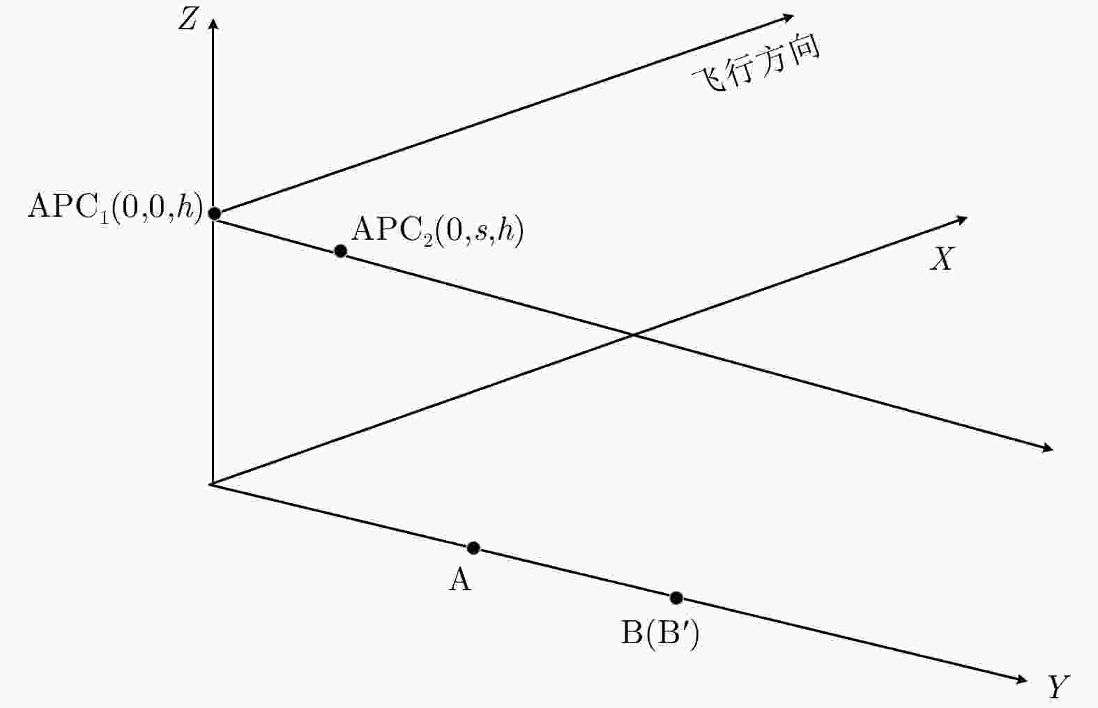
    图  2  距离向抗欺骗干扰几何模型

    Figure  2.  Geometric model of range anti-deception jamming

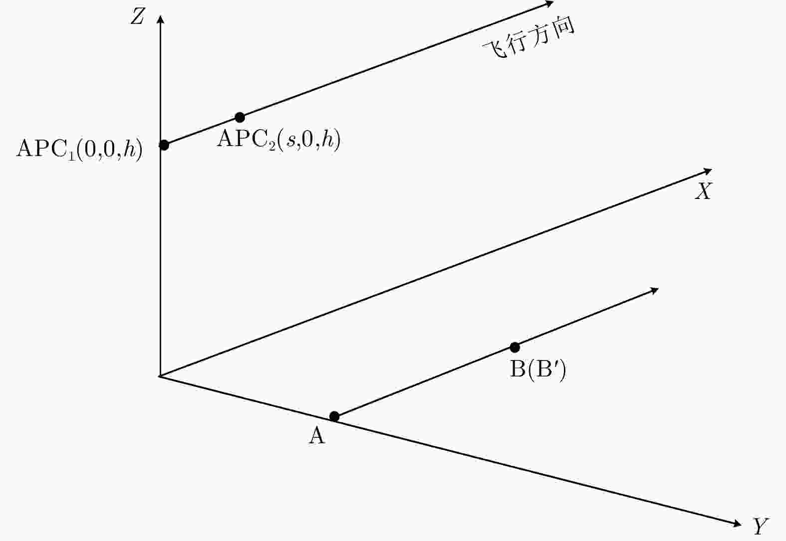
    图  3  方位向抗欺骗干扰几何模型

    Figure  3.  Geometric model of azimuth anti-deception jamming

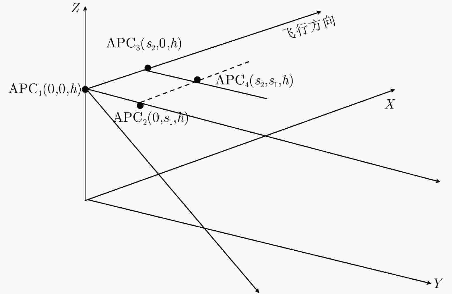
    图  4  2维抗欺骗干扰几何模型

    Figure  4.  Geometric model for two-dimensional anti-deception jamming

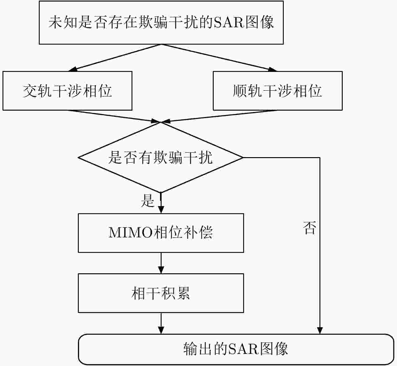
    图  5  方法流程

    Figure  5.  Method flow

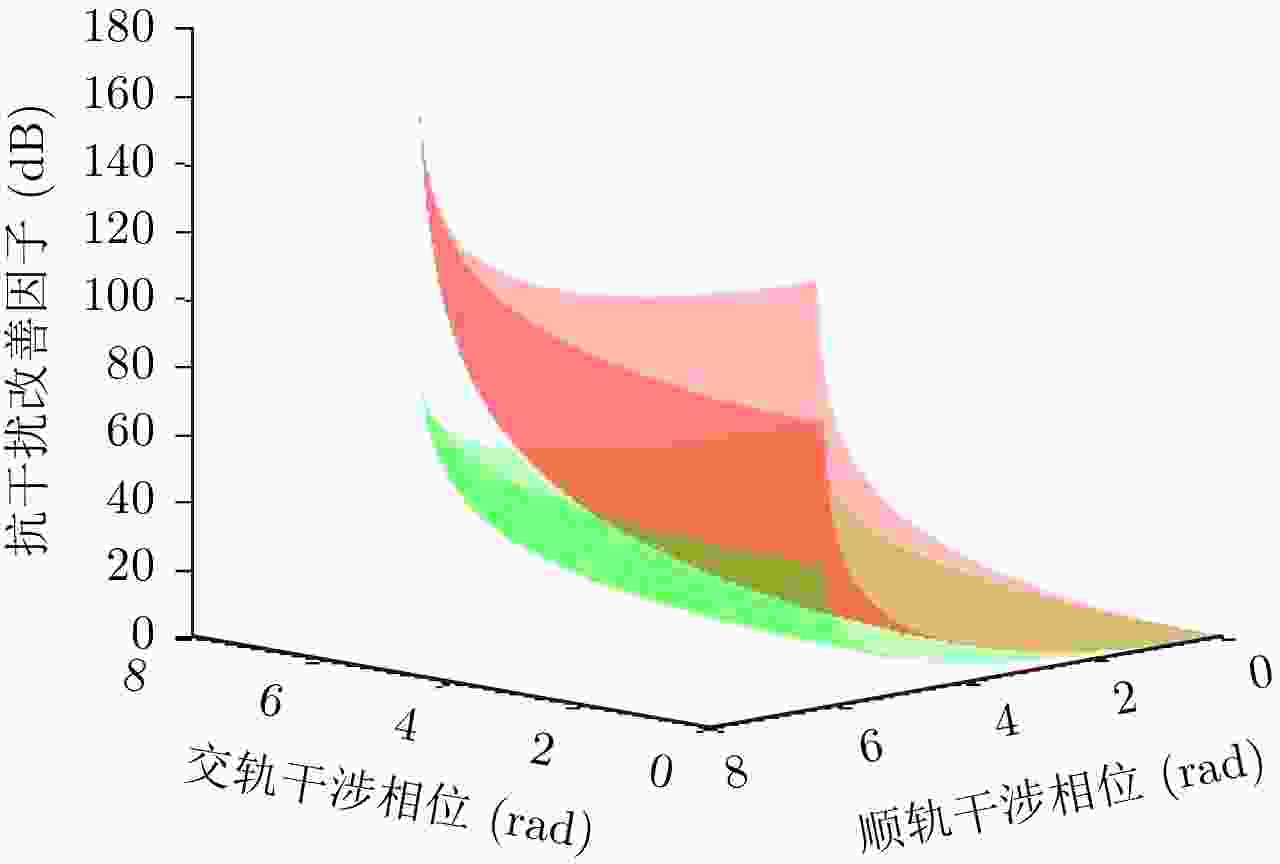
    图  6  4发4收与单发4收对比

    Figure  6.  Comparison of 4-in-4-out and 4-in-1-out

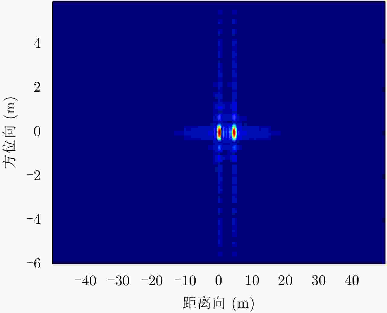
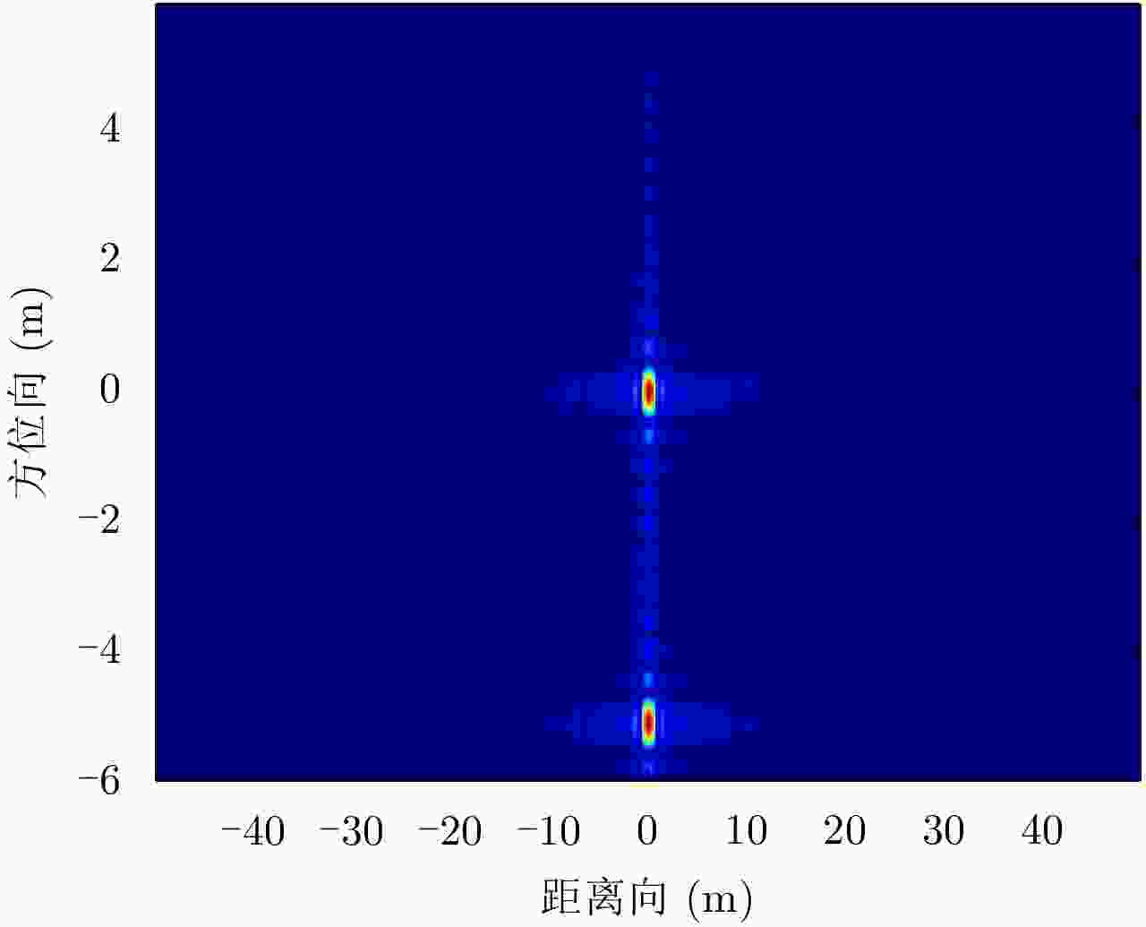
    图  7  点目标成像

    Figure  7.  Point target imaging

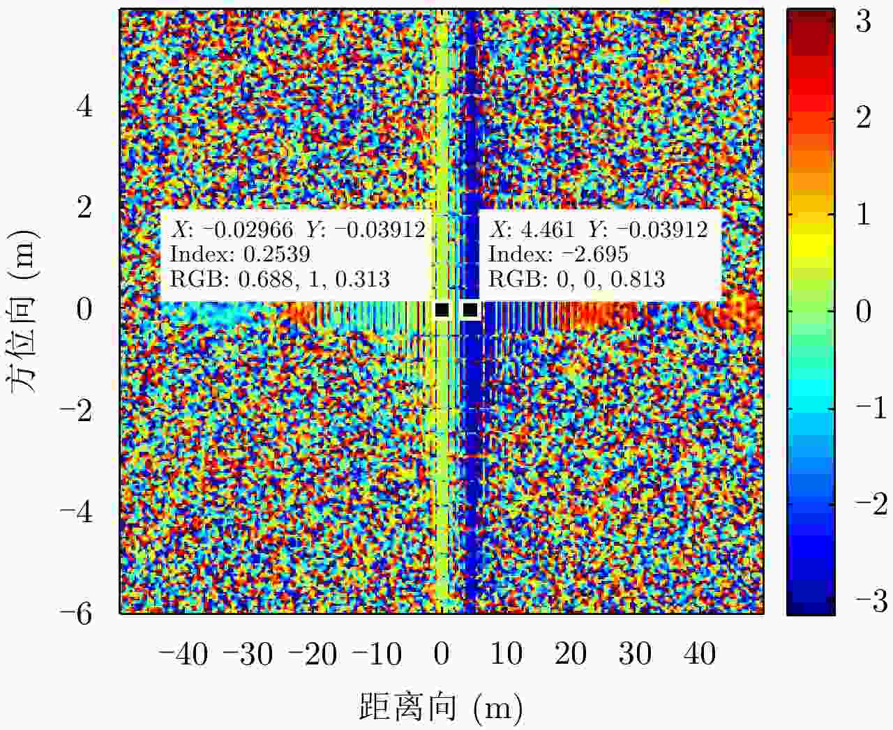
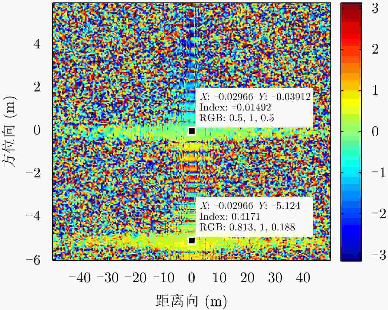
    图  8  真实目标干涉相位

    Figure  8.  Interferometric phase of real target

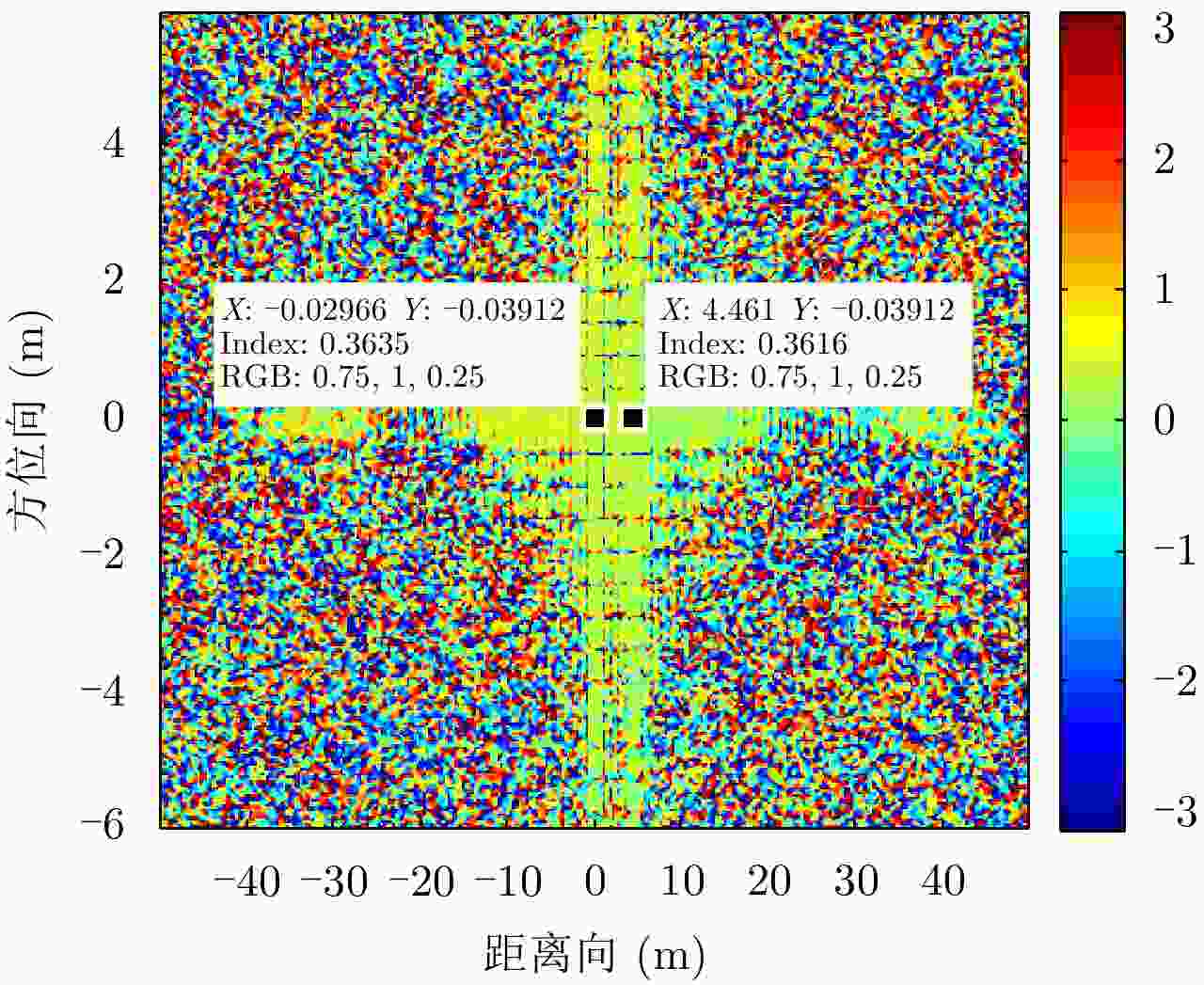
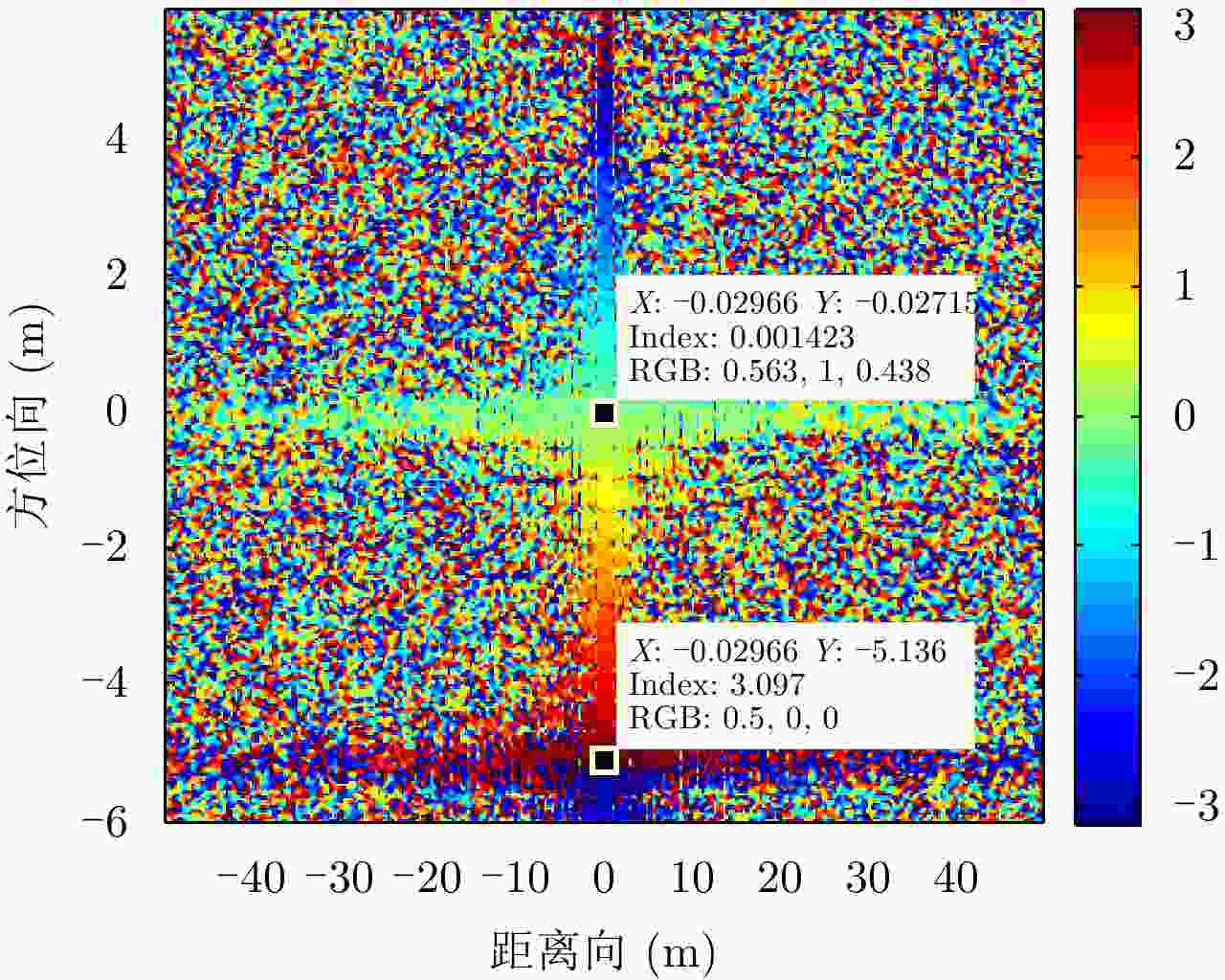
    图  9  干扰目标干涉相位

    Figure  9.  Interferometric phase of jamming target

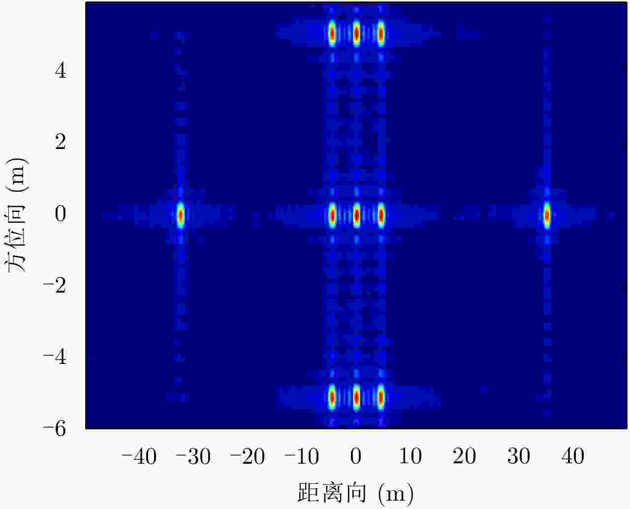
    图  10  点目标成像

    Figure  10.  Point target imaging

    图  11  真实目标干涉相位

    Figure  11.  Interferometric phase of real target

    图  12  干扰目标干涉相位

    Figure  12.  Interferometric phase of jamming target

    图  13  干扰目标成像

    Figure  13.  Jamming target imaging

    图  14  抗干扰后目标成像

    Figure  14.  Target imaging after anti-jamming

    表  1  仿真参数

    Table  1.   Simulation parameters

    参数数值
    景中心斜距(km)1.414
    雷达有效速度(m/s)150
    发射脉冲时宽(μs)2.5
    距离调频率(Hz/s)20 × 1012
    雷达工作频率(GHz)5.3
    多普勒带宽(Hz)80
    距离采样率(MHz)60
    方位采样率(Hz)400
    回波信噪比(dB)10
    距离基线长度(m)4
    方位基线长度(m)2
    下载: 导出CSV

    表  2  9点目标交轨干涉相位

    Table  2.   Cross-track interference phase of nine-point target

    相位(rad)第1列第2列第3列
    第1行0.13480.13700.1423
    第2行0.13600.13900.1407
    第3行0.13790.13700.1425
    下载: 导出CSV

    表  3  9点目标顺轨干涉相位

    Table  3.   Along-track interference phase of nine-point target

    相位(rad)第1列第2列第3列
    第1行3.0853.0853.085
    第2行000
    第3行–3.085–3.086–3.086
    下载: 导出CSV
  • [1] 朱守保, 罗强, 童创明. SAR图像欺骗干扰方法研究[J]. 电光与控制, 2012, 19(4): 39–42. doi: 10.3969/j.issn.1671-637X.2012.04.010

    ZHU Shoubao, LUO Qiang, and TONG Chuangming. Methods of deceptive jamming to SAR image[J]. Electronics Optics &Control, 2012, 19(4): 39–42. doi: 10.3969/j.issn.1671-637X.2012.04.010
    [2] ZHANG Jindong, ZHU Daiyin, and ZHANG Gong. New antivelocity deception jamming technique using pulses with adaptive initial phases[J]. IEEE Transactions on Aerospace and Electronic Systems, 2013, 49(2): 1290–1300. doi: 10.1109/TAES.2013.6494414
    [3] 孙光才, 周峰, 邢孟道, 等. 虚假场景SAR欺骗式干扰技术及实时性分析[J]. 西安电子科技大学学报(自然科学版), 2009, 36(5): 813–818, 866.

    SUN Guangcai, ZHOU Feng, XING Mengdao, et al. Deception-jamming technology against the SAR based on the deceptive scene and real-time analyses[J]. Journal of Xidian University, 2009, 36(5): 813–818, 866.
    [4] 马晓岩, 秦江敏, 贺照辉, 等. 抑制SAR压制性干扰的三通道对消方法[J]. 电子学报, 2007, 35(6): 1015–1020. doi: 10.3321/j.issn:0372-2112.2007.06.002

    MA Xiaoyan, QIN Jiangmin, HE Zhaohui, et al. Three-channel cancellation of SAR blanketing jamming suppression[J]. Acta Electronica Sinica, 2007, 35(6): 1015–1020. doi: 10.3321/j.issn:0372-2112.2007.06.002
    [5] ZHOU F, SUN G, BAI X, et al. A novel method for adaptive SAR barrage jamming suppression[J]. IEEE Geoscience and Remote Sensing Letters, 2012, 9(2): 292–296. doi: 10.1109/LGRS.2011.2166753
    [6] 王晓东, 马泉成. 基于FMCW合成孔径雷达抗欺骗干扰方法研究[J]. 计算机仿真, 2013, 30(7): 5–10. doi: 10.3969/j.issn.1006-9348.2013.07.002

    WANG Xiaodong and MA Quancheng. Anti-deception jamming method for frequency modulated continuous wave synthetic aperture radar[J]. Computer Simulation, 2013, 30(7): 5–10. doi: 10.3969/j.issn.1006-9348.2013.07.002
    [7] 彭发祥, 李宏伟, 蔡斌, 等. 星载多发多收SAR成像和抗欺骗干扰研究[J]. 现代防御技术, 2012, 40(2): 143–149, 154. doi: 10.3969/j.issn.1009-086x.2012.02.028

    PENG Faxiang, LI Hongwei, CAI Bin, et al. Research on spaceborne MIMO-SAR imaging and anti-deceptive jamming[J]. Modern Defence Technology, 2012, 40(2): 143–149, 154. doi: 10.3969/j.issn.1009-086x.2012.02.028
    [8] 齐维孔, 禹卫东. 距离向DBF-SAR系统抗欺骗干扰研究[J]. 电子与信息学报, 2010, 32(12): 2830–2835. doi: 10.3724/SP.J.1146.2010.00074

    QI Weikong and YU Weidong. Research on countering deceptive jamming with range DBF-SAR system[J]. Journal of Electronics &Information Technology, 2010, 32(12): 2830–2835. doi: 10.3724/SP.J.1146.2010.00074
    [9] SOUMEKH M. SAR-ECCM using phase-perturbed LFM chirp signals and DRFM repeat jammer penalization[J]. IEEE Transactions on Aerospace and Electronic Systems, 2006, 42(1): 191–205. doi: 10.1109/TAES.2006.1603414
    [10] Emmanuel Arturo Solis Nepote. Chaotic and chaotic based frequency modulated signals for radar imaging[D]. [Master dissertation], University of Manitoba, 2003.
    [11] LI Chen and ZHU Daiyin. The detection of deception jamming against SAR based on dual-aperture antenna cross-track interferometry[C]. 2006 CIE International Conference on Radar, Shanghai, China, 2006: 1–4. doi: 10.1009/ICR.2006.343274.
    [12] QIN Jiangmin, YANG Jun, HE Zhaohui, et al. Analysis of target loss due to suppressing SAR jamming using dual-channel cancellation[C]. 2006 CIE International Conference on Radar, Shanghai, China, 2006: 1–4. doi: 10.1109/ICR.2006.343324.
    [13] SUN Bingzhang and LI Jingwen. A new interference elimination method for multi-satellite SAR system[C]. IGARSS 2008 IEEE International Geoscience and Remote Sensing Symposium, Boston, MA, USA, 2008, 4: IV-1316–IV-1319. doi: 10.1109/IGARSS.2008.4779973
    [14] ZHAO Bo, HUANG Lei, LI Jian, et al. Target reconstruction from deceptively jammed single-channel SAR[J]. IEEE Transactions on Geoscience and Remote Sensing, 2018, 56(1): 152–167. doi: 10.1109/TGRS.2017.2744178
    [15] 王杰, 丁赤飚, 梁兴东, 等. 机载同时同频MIMO-SAR系统研究概述[J]. 雷达学报, 2018, 7(2): 220–234. doi: 10.12000/JR17046

    WANG Jie, DING Chibiao, LIANG Xingdong, et al. Research outline of airborne MIMO-SAR system with same time-frequency coverage[J]. Journal of Radars, 2018, 7(2): 220–234. doi: 10.12000/JR17046
    [16] 黄洪旭, 黄知涛, 周一宇. 对合成孔径雷达的移频干扰研究[J]. 宇航学报, 2006, 27(3): 463–468. doi: 10.3321/j.issn:1000-1328.2006.03.027

    HUANG Hongxu, HUANG Zhitao, and ZHOU Yiyu. A study on the shift-frequency jamming to SAR[J]. Journal of Astronautics, 2006, 27(3): 463–468. doi: 10.3321/j.issn:1000-1328.2006.03.027
    [17] HE Xiaodong, WANG Zhen, and TANG Bin. Two-dimensional frequency modulation jamming to SAR based on ship-borne jammer[J]. International Journal of Electronics Letters, 2016, 4(2): 141–157. doi: 10.1080/00207217.2014.966782
    [18] 许宝民, 郑光勇, 李宏. 合成孔径雷达有源欺骗干扰仿真分析[J]. 飞行器测控学报, 2010, 29(3): 84–87.

    XU Baomin, ZHENG Guangyong, and LI Hong. Simulation research on active deceptive jamming to SAR[J]. Journal of Spacecraft TT &C Technology, 2010, 29(3): 84–87.
    [19] 刘永才, 王伟, 潘小义, 等. 基于延迟-移频的SAR有源欺骗干扰有效区域研究[J]. 雷达学报, 2013, 2(1): 46–53. doi: 10.3724/SP.J.1300.2012.13001

    LIU Yongcai, WANG Wei, PAN Xiaoyi, et al. Effective region of active decoy jamming to SAR based on time-delay doppler-shift method[J]. Journal of Radars, 2013, 2(1): 46–53. doi: 10.3724/SP.J.1300.2012.13001
  • 期刊类型引用(4)

    1. 葛津津,周浩,凌天庆. 一种应用于脉冲探地雷达前端的探测子系统. 电子测量技术. 2022(04): 27-32 . 百度学术
    2. 尹诗,郭伟. 用于探地雷达的超宽带天线设计与仿真. 电子设计工程. 2018(03): 98-102 . 百度学术
    3. 宋立伟,张超,洪涛. 冲击波载荷对平面阵列天线电性能的影响. 电子机械工程. 2017(04): 1-5+58 . 百度学术
    4. 尹德,叶盛波,刘晋伟,纪奕才,刘小军,方广有. 一种用于高速公路探地雷达的新型时域超宽带TEM喇叭天线. 雷达学报. 2017(06): 611-618 . 本站查看

    其他类型引用(6)

  • 加载中
图(14) / 表(3)
计量
  • 文章访问数: 2793
  • HTML全文浏览量: 918
  • PDF下载量: 174
  • 被引次数: 10
出版历程
  • 收稿日期:  2018-12-21
  • 修回日期:  2019-02-22
  • 网络出版日期:  2019-02-28

目录

/

返回文章
返回