Analysis on the Transmit Distortion of the Circular Polarized Wave Based on the Axial Ratio Parameter
-
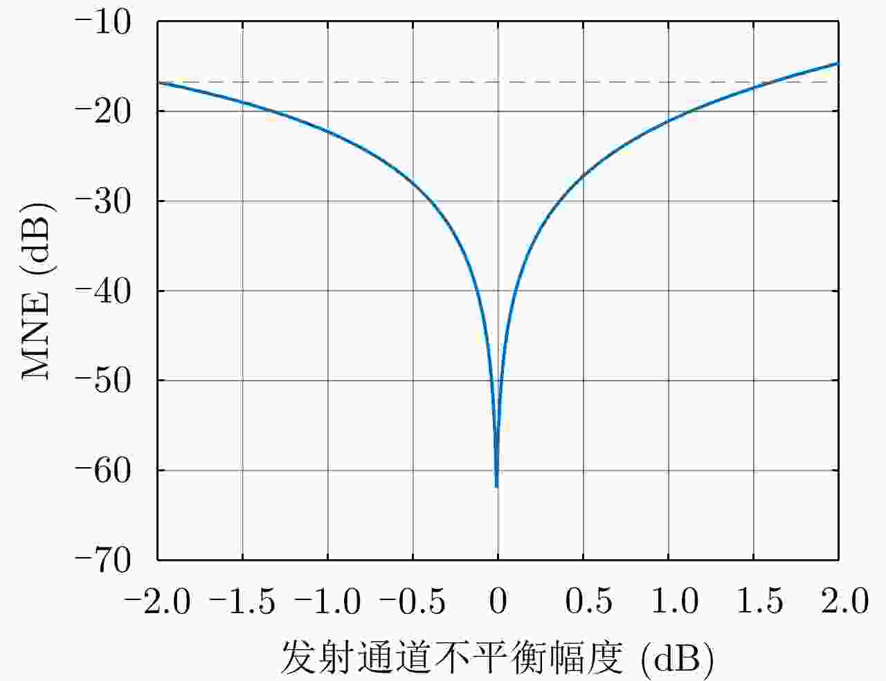
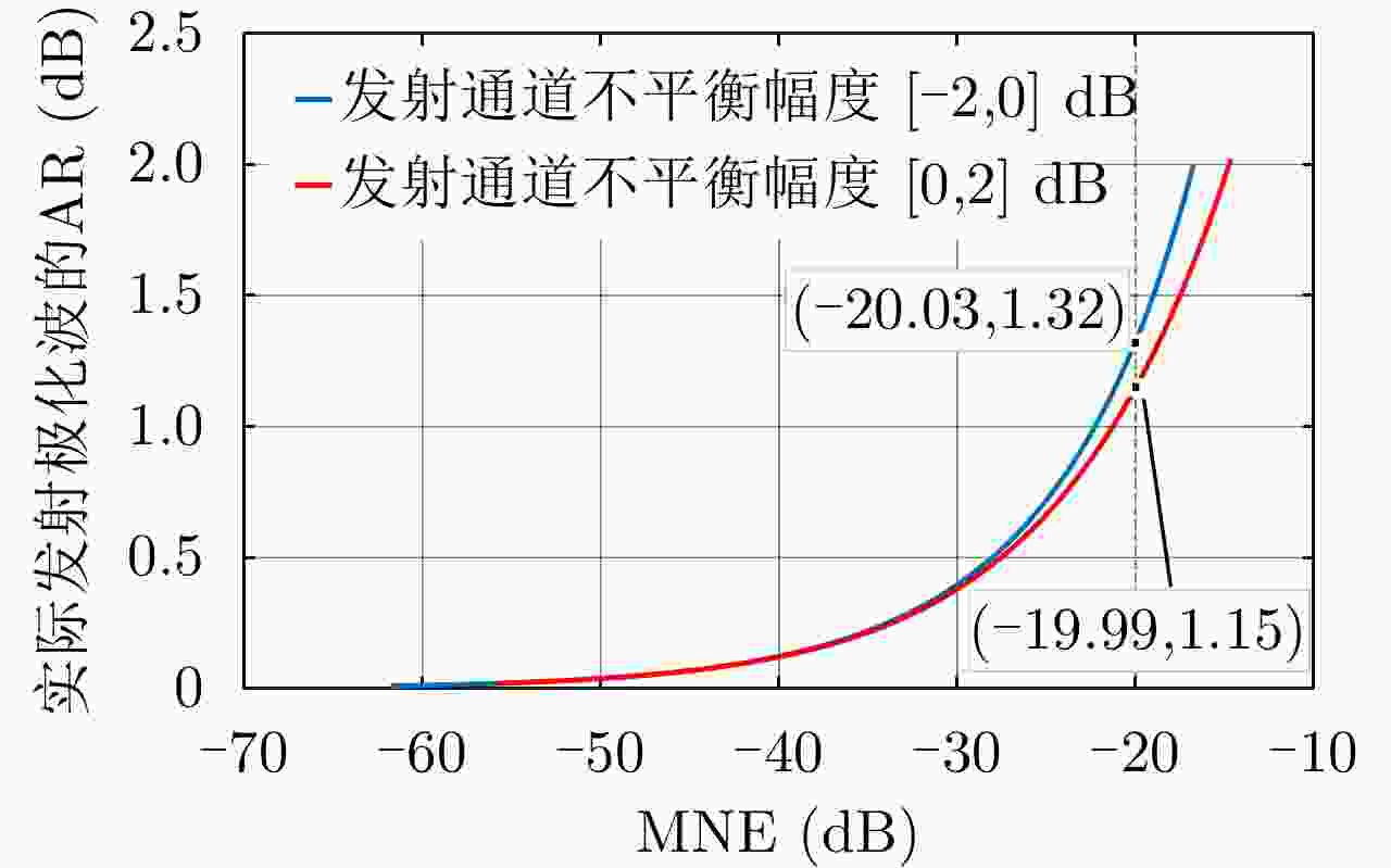
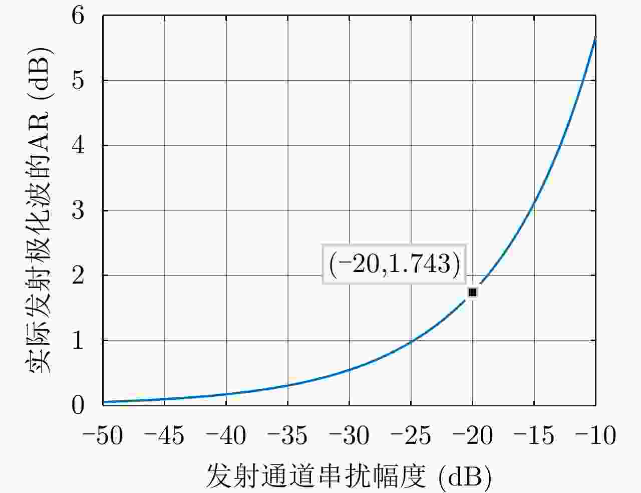
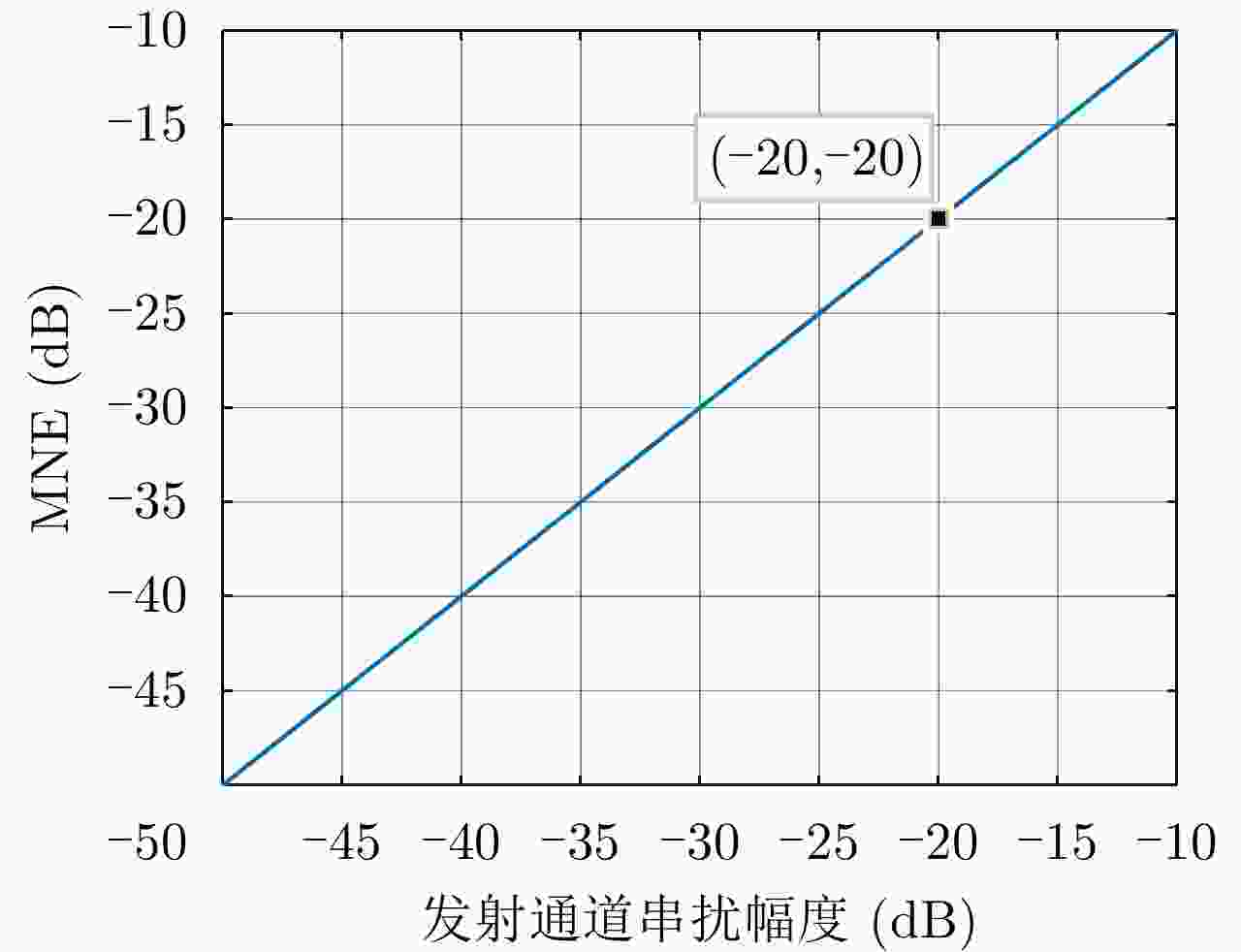
摘要: 简缩极化(CP)模式是一种新型双极化模式。在实际工程应用中,包括简缩极化模式在内的所有双极化模式均无法直接通过外定标的方法补偿发射误差。因而有必要对发射误差所带来的影响进行详细分析。针对极化SAR系统,目前已有学者提出使用误差的最大归一化误差(MNE)参数对极化SAR系统的极化质量做分析评估。该文针对发射圆极化波的简缩极化模式提出了一种基于实际发射极化波极化轴比(AR)参数的发射误差分析方法。首先,通过仿真分析不同发射误差源对AR参数的影响,与此同时还展示了相同发射误差源影响下的MNE参数;通过分析对比,总结了AR参数相对MNE参数的3个优点;最后,使用高分三号卫星的实际测量误差数据与圆极化发射波实验系统的实测数据验证了该文提出的发射误差评估方法的有效性。Abstract: Compact Polarimetric (CP) mode is a new dual-pol mode introduced in the last decade. The main current CP mode transmits circular polarized waves. Data in the form of Stokes parameters obtained by this mode has rotational invariance. In real engineering applications, transmit distortions in all dual-pol modes, including the CP mode, cannot be directly compensated with external calibration methods. Therefore, it is necessary to analysis the influences caused by transmit distortions. Until now, the Maximum Normalized Error (MNE) parameter has already been proposed by existing researches to analyze polarimetric quality of the Polarimetric SAR (PolSAR) system. This paper has proposed an analysis method to analysis the influence of transmit distortions in polarimetric modes with circular polarimetric wave in transmission, based on the Axial Ratio (AR) parameter of real transmitted wave. Firstly, this paper has analyzed the influence of different transmit distortion sources to AR parameter with simulations. Meanwhile, this part has also demonstrated the influence of same distortion sources to the MNE parameter. Through comparison of this two results, this paper has concluded three advantages of the AR parameter over the MNE parameter. At last, the effectiveness of the proposed evaluation method has been verified using real measured GF-3 distortion data and test data obtained by experimental system, which transmit circular polarized waves.
-
表 1 高分三号在轨定标试验的实测发射误差与对应的AR与MNE参数
Table 1. Measured transmit distortion of GF-3 on-orbit calibration experiment and corresponding AR and MNE parameters
实验时间 T11 T12 T21 T22 AR (dB) MNE (dB) 2016.09.08 1.0∠0.0° 0.0149∠–45.2715° 0.0040∠168.4078° 0.9133∠19.3436° 3.0751 –12.4789 2016.09.19 1.0∠0.0° 0.0152∠–92.6368° 0.0026∠–49.6355° 0.8752∠8.6810° 1.8590 –17.4527 2017.07.11 1.0∠0.0° 0.0126∠–69.1254° 0.0042∠–177.2737° 0.9431∠10.4461° 1.7046 –17.4304 2017.07.16 1.0∠0.0° 0.0131∠–54.6146° 0.0032∠–178.2101° 0.9382∠11.0117° 0.6557 –26.6122 表 2 第1次发射通道部分测试结果
Table 2. Partial measured results of the first transmit channel test
编号 调幅设置(dB) 调相设置(°) x通道幅度(dB) x通道相位(°) y通道幅度(dB) y通道相位(°) 幅度比(dB) 相位差(°) AR参数(dB) 1 2.5 5.625 –13.3275 –40.4487 –13.4555 –132.3204 0.1281 91.8717 0.3114 2 2.5 185.625 –13.3081 139.3082 –13.4567 –132.3170 0.1486 –88.3748 0.2878 3 3.0 11.250 –13.5909 –45.1950 –13.4556 –132.3143 –0.1353 87.1193 0.4574 4 3.0 191.250 –13.5295 134.5363 –13.4578 –132.3216 –0.0717 –93.1422 0.4819 表 3 第2次发射通道部分测试结果
Table 3. Partial measured results of the second transmit channel test
编号 调幅设置(dB) 调相设置(°) x通道幅度(dB) x通道相位(°) y通道幅度(dB) y通道相位(°) 幅度比(dB) 相位差(°) AR参数(dB) 1 2.5 5.625 –13.3411 –39.9068 –13.4518 –131.8972 0.1106 91.9904 0.3214 2 2.5 185.625 –13.3186 139.9906 –13.4539 –131.8965 0.1353 –88.1129 0.3165 3 3.0 11.250 –13.6044 –44.5745 –13.4533 –131.8974 –0.1511 87.3299 0.4332 4 3.0 191.250 –13.5426 135.2489 –13.4533 –131.8920 –0.0894 –92.8591 0.4427 -
[1] MOREIRA A, PRATS-IRAOLA P, YOUNIS M, et al. A tutorial on synthetic aperture radar[J]. IEEE Geoscience and Remote Sensing Magazine, 2013, 1(1): 6–43. doi: 10.1109/MGRS.2013.2248301 [2] CHEN Siwei, LI Yongzhen, WANG Xuesong, et al. Modeling and interpretation of scattering mechanisms in polarimetric synthetic aperture radar: Advances and perspectives[J]. IEEE Signal Processing Magazine, 2014, 31(4): 79–89. doi: 10.1109/MSP.2014.2312099 [3] CHARBONNEAU F J, BRISCO B, RANEY R K, et al. Compact polarimetry overview and applications assessment[J]. Canadian Journal of Remote Sensing, 2010, 36(Suppl 2): S298–S315. doi: 10.5589/M10-062 [4] SOUYRIS J C, IMBO P, FJØRTOFT R, et al. Compact polarimetry based on symmetry properties of geophysical media: The $\pi $ /4 mode[J]. IEEE Transactions on Geoscience and Remote Sensing, 2005, 43(3): 634–646. doi: 10.1109/TGRS.2004.842486[5] STACY N and PREISS M. Compact polarimetric analysis of X-band SAR data[C]. The 6th European Conference on Synthetic Aperture Radar, Dresden, Germany, 2006. [6] RANEY R K. Hybrid-polarity SAR architecture[J]. IEEE Transactions on Geoscience and Remote Sensing, 2007, 45(11): 3397–3404. doi: 10.1109/TGRS.2007.895883 [7] 洪文. 基于混合极化架构的极化SAR: 原理与应用(中英文)[J]. 雷达学报, 2016, 5(6): 559–595. doi: 10.12000/JR16074HONG Wen. Hybrid-polarity architecture based polarimetric SAR: Principles and applications (in Chinese and in English)[J]. Journal of Radars, 2016, 5(6): 559–595. doi: 10.12000/JR16074 [8] RANEY R K. Comparing compact and quadrature polarimetric SAR performance[J]. IEEE Geoscience and Remote Sensing Letters, 2016, 13(6): 861–864. doi: 10.1109/LGRS.2016.2550863 [9] RANEY R K, SPUDIS P D, BUSSEY B, et al. The lunar mini-RF radars: Hybrid polarimetric architecture and initial results[J]. Proceedings of the IEEE, 2011, 99(5): 808–823. doi: 10.1109/JPROC.2010.2084970 [10] MISRA T and KIRANKUMAR A S. RISAT-1: Configuration and performance evaluation[C]. 2014 XXXIth URSI General Assembly and Scientific Symposium, Beijing, China, 2014: 1–4. doi: 10.1109/URSIGASS.2014.6929612. [11] KANKAKU Y, OSAWA Y, SUZUKI S, et al. The overview of the L-band SAR onboard ALOS-2[C]. The Progress in Electromagnetics Research Symposium, Moscow, Russia, 2009: 735–738. [12] TOUZI R and CHARBONNEAU F. Requirements on the calibration of hybrid-compact SAR[C]. 2014 IEEE Geoscience and Remote Sensing Symposium, Quebec City, Canada, 2014: 1109–1112. doi: 10.1109/IGARSS.2014.6946623 [13] THOMPSON A A. Overview of the RADARSAT constellation mission[J]. Canadian Journal of Remote Sensing, 2015, 41(5): 401–407. doi: 10.1080/07038992.2015.1104633 [14] WANG Yanting, AINSWORTH T L, and LEE J S. Assessment of system polarization quality for polarimetric SAR imagery and target decomposition[J]. IEEE Transactions on Geoscience and Remote Sensing, 2011, 49(5): 1755–1771. doi: 10.1109/TGRS.2010.2087342 [15] GUO Shenglong, ZHANG Jingjing, LI Yang, et al. Effects of polarization distortion at transmission and faraday rotation on compact polarimetric SAR system and H/ $\bar \alpha $ decomposition[J]. IEEE Geoscience and Remote Sensing Letters, 2015, 12(8): 1700–1704. doi: 10.1109/LGRS.2015.2420116[16] LEE J S and POTTIER E. Polarimetric Radar Imaging: From Basics to Applications[M]. Boca Raton: CRC press, 2009. [17] 陈琳, 张晶晶, 李洋, 等. 单发双收SAR系统通用极化定标算法[J]. 雷达学报, 2012, 1(3): 323–328. doi: 10.3724/SP.J.1300.2012.20062CHEN Lin, ZHANG Jingjing, LI Yang, et al. General calibration algorithm for single-transmitting-dual-receiving polarimetric SAR system[J]. Journal of Radars, 2012, 1(3): 323–328. doi: 10.3724/SP.J.1300.2012.20062 [18] JIANG Sha, QIU Xiaolan, HAN Bing, et al. Error source analysis and correction of GF-3 polarimetric data[J]. Remote Sensing, 2018, 10(11): 1685. doi: 10.3390/rs10111685 [19] WRIGHT P A, QUEGAN S, WHEADON N S, et al. Faraday rotation effects on L-band spaceborne SAR data[J]. IEEE Transactions on Geoscience and Remote Sensing, 2003, 41(12): 2735–2744. doi: 10.1109/TGRS.2003.815399 [20] FREEMAN A and SAATCHI S S. On the detection of faraday rotation in linearly polarized L-band SAR backscatter signatures[J]. IEEE Transactions on Geoscience and Remote Sensing, 2004, 42(8): 1607–1616. doi: 10.1109/TGRS.2004.830163 [21] LIANG Weibin, JIA Zengzeng, QIU Xiaolan, et al. Polarimetric calibration of the GaoFen-3 mission using active radar calibrators and the applicable conditions of system model for radar polarimeters[J]. Remote Sensing, 2019, 11(2): 176. doi: 10.3390/rs11020176 [22] MCKERRACHER P L, JENSEN J R, SEQUEIRA H B, et al. Mini-RF calibration, a unique approach to on-orbit synthetic aperture radar system calibration[C]. The 41st Lunar and Planetary Science Conference, The Woodlands, USA, 2010: 2352. -


 作者中心
作者中心 专家审稿
专家审稿 责编办公
责编办公 编辑办公
编辑办公
 下载:
下载:

