A Novel Wireless Internal Calibration Method of Spaceborne SAR
-
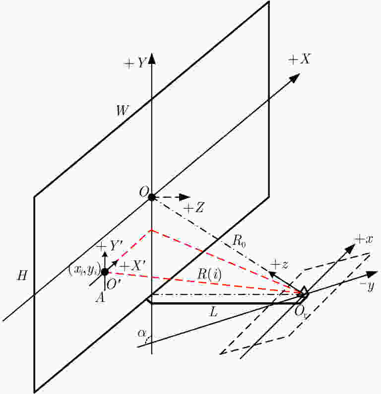
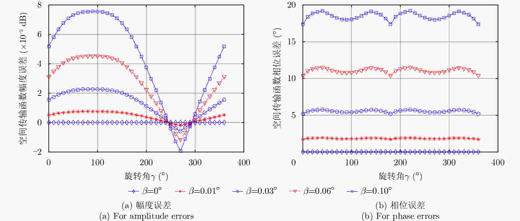
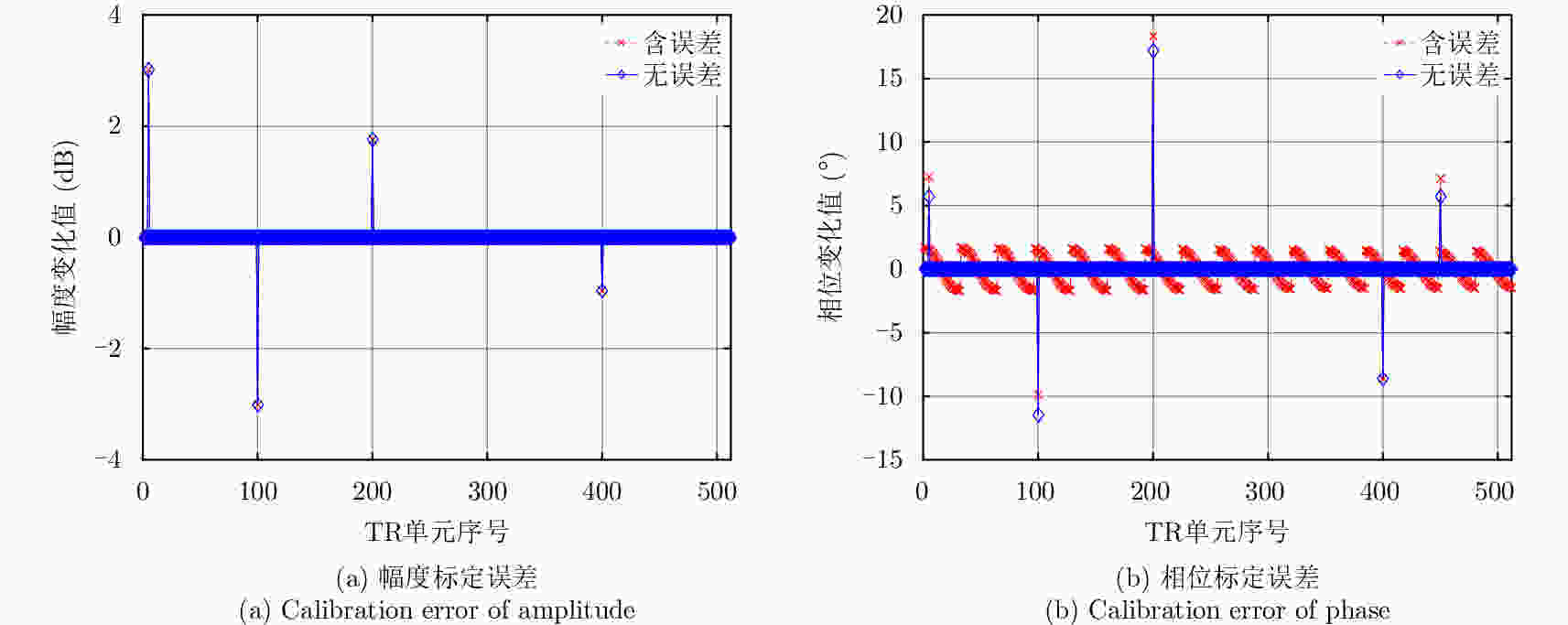
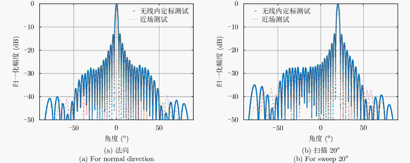
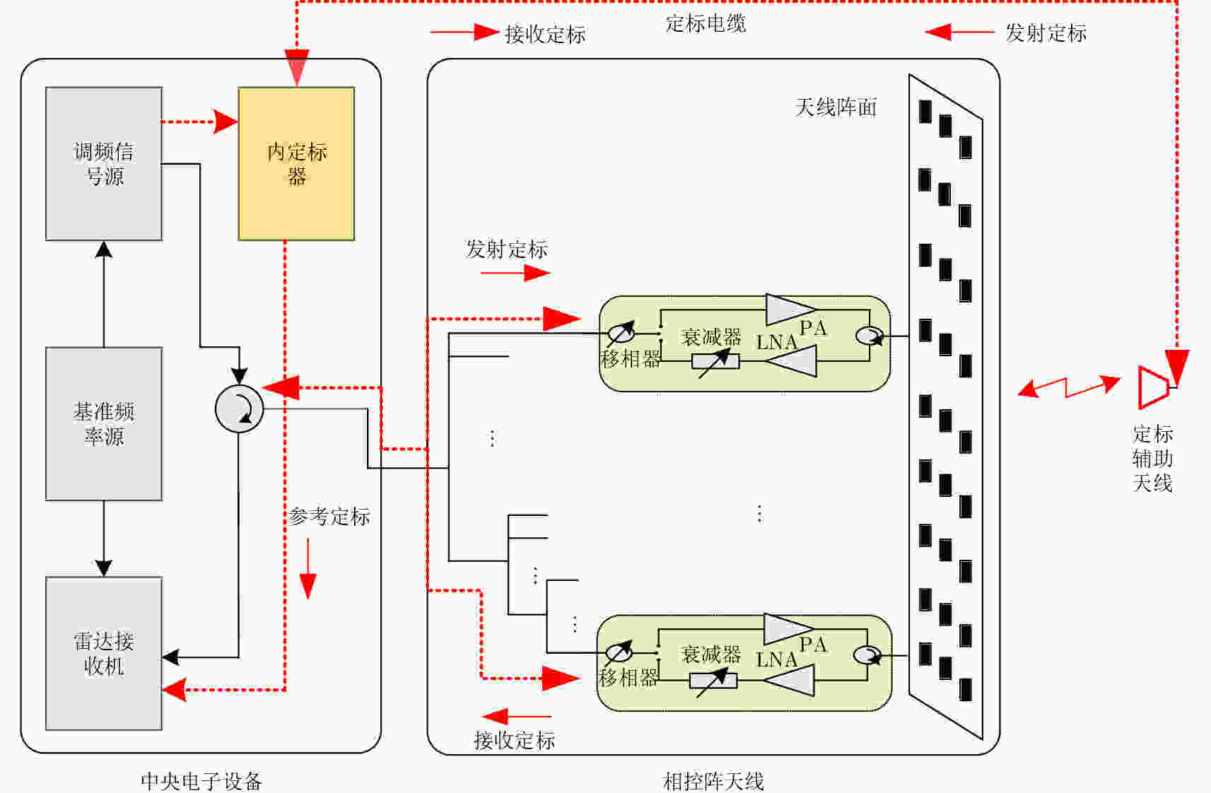
摘要: 内定标利用雷达系统内部设备和定标通路来测量系统各部分幅度和相位在成像过程中的相对变化,是保证雷达图像辐射精度的重要手段。该文针对传统有线内定标方案定标通路未覆盖相控阵天线TR输出端至无源阵面路径、定标网络庞大且自身误差控制难等不足,提出了一种新颖的利用辅助天线的无线内定标方法,给出了定标原理和分析模型,推导了SAR天线TR通道幅相特性和系统传递函数的标定方法,并在典型星载SAR系统参数下对标定误差进行了仿真分析,仿真结果表明,辅助天线支撑杆位置引起的TR通道幅度标定误差在10–3 dB量级,可以忽略;引起相位标定误差与支撑杆位置偏差密切相关,可依据文中给出的仿真曲线得到。支持杆位置引起的系统传递函数幅度标定误差小于0.1 dB;引起的相位标定误差对支撑杆位置偏差不敏感。最后在实际相控阵天线上对无线内定标方法进行了验证,获取了TR通道幅相特性标定的实测结果,表明了该方案的可行性和有效性。Abstract: Internal calibration measures the changes in amplitude and phase of a system during imaging via the calibration loop built in Synthetic Aperture Radar (SAR). Internal calibration is also an important factor to improve the radiation accuracy of the radar. In this study, a novel wireless internal calibration method with auxiliary antenna is presented, considering that the traditional scheme is inefficient, as the calibration loop cannot cover the path from the TR (Transmitter-Receiver) output to the antenna radiator. The calibration loop also results in a complicated and heavy network. The principle and model of the new method is given, and the TR performance and system transfer function calibration approach are deduced. In addition, error analysis is conducted. The simulation results show that TR amplitude calibration errors caused by the rod of auxiliary antenna are at a 10–3 dB level, and phase calibration errors are obtained from the simulation curve in the paper; transfer function amplitude calibration errors are less than 0.1 dB, and phase calibration errors are not sensitive to the bias of the rod. Finally, the simulation results based on typical parameters of spaceborne SAR and the individual TR calibration experiments confirm the availability and feasibility of this novel method.
-
表 1 TR通道幅相特性标定误差源
Table 1. Error sources of TR amplitude and phase calibration
误差项 误差代号 幅度(dB) 相位(°) 空间传输函数误差 $\Delta S\left( i \right)$ $\Delta {A_S}\left( i \right)$ $\Delta {\varphi _S}\left( i \right)$ 移相器误差 $\Delta P\left( {i{\rm{,}}k} \right)$ $\Delta A\left( {i{\rm{,}}k} \right)$ $\Delta \varphi \left( {i{\rm{,}}k} \right)$ 表 2 系统传递函数标定误差源
Table 2. Error sources of transfer function calibration
误差项 误差代号 幅度(dB) 相位(°) 定标电缆的误差 $\Delta {C_L}$ $\Delta {A_{{\rm{CL}}}}$ $\Delta {\varphi _{{\rm{CL}}}}$ 内定标器误差 参考定标回路 $\Delta {\rm{C}}{{\rm{R}}_{\rm{1}}}$ $\Delta {A_{{\rm{CR1}}}}$ $\Delta {\varphi _{{\rm{CR1}}}}$ 发射定标回路 $\Delta {\rm{C}}{{\rm{R}}_{\rm{2}}}$ $\Delta {A_{{\rm{CR2}}}}$ $\Delta {\varphi _{{\rm{CR2}}}}$ 接收定标回路 $\Delta {\rm{C}}{{\rm{R}}_{\rm{3}}}$ $\Delta {A_{{\rm{CR3}}}}$ $\Delta {\varphi _{{\rm{CR3}}}}$ 传输函数矢量和误差 $\Delta \delta = \Delta \left\{ {\sum\nolimits_{i = 1}^N {{S_C}\left( i \right)S\left( i \right)} } \right\}$ $\Delta {A_\delta }$ $\Delta {\varphi _\delta }$ 表 3 仿真参数设置
Table 3. Parameters of simulation
参数名称 参数代号 参数值 工作频段 f X波段 天线长度 W 5 m 天线高度 H 1 m 支撑杆长度 L 1 m 方位向单元数 M 32 距离向单元数 N 16 支撑杆位置误差 $\beta $ 0°~0.10° 支撑杆旋转角 $\gamma $ 0°~360° 辅助天线形式 / 开口波导 辐射单元形式 / 波导缝隙 内定标器误差(幅度) / 0.4 dB 内定标器误差(相位) / 2.0° 定标电缆误差(幅度) / 0.1 dB 定标电缆误差(相位) / 1° 表 4 系统传递函数标定误差
Table 4. Errors of system transfer function calibration
支撑杆位置误差 $\beta $(°) 传递函数标定误差 幅度(dB) 相位(°) 0 0.447 2.828 0.01 0.448 2.829 0.02 0.449 2.829 0.03 0.453 2.831 0.04 0.459 2.832 0.06 0.485 2.832 0.08 0.535 2.837 0.10 0.616 2.844 -
[1] 邓云凯, 赵凤军, 王宇. 星载SAR技术的发展趋势及应用浅析[J]. 雷达学报, 2012, 1(1): 1–10. DOI: 10.3724/SP.J.1300.2012.20015Deng Yun-kai, Zhao Feng-jun, and Wang Yu. Brief analysis on the development and application of spaceborne SAR[J]. Journal of Radars, 2012, 1(1): 1–10. DOI: 10.3724/SP.J.1300.2012.20015 [2] 李春升, 王伟杰, 王鹏波, 等. 星载SAR技术的现状与发展趋势[J]. 电子与信息学报, 2016, 38(1): 229–240. DOI: 10.11999/JEIT151116Li Chun-sheng, Wang Wei-jie, Wang Peng-bo, et al. Current situation and development trends of spaceborne SAR technology[J]. Journal of Electronics&Information Technology, 2016, 38(1): 229–240. DOI: 10.11999/JEIT151116 [3] 袁孝康. 星载合成孔径雷达导论[M]. 北京: 国防工业出版社, 2003Yuan Xiao-kang. Introduce to the Spaceborne Sythetic Aperture Radar[M]. Beijing: National Defend Industry Press, 2003 [4] 杨汝良, 戴博伟, 谈璐璐, 等. 极化微波成像[M]. 北京: 国防工业出版社, 2017Yang Ru-liang, Dai Bo-wei, Tan Lu-lu, et al.. Polarimetric Microwave Imaging[M]. Beijing: National Defend Industry Press, 2017 [5] Brautigam B, Gonzalez J H, Schwerdt M, et al. TerraSAR-X instrument calibration results and extension for TanDEM-X[J]. IEEE Transactions on Geoscience and Remote Sensing, 2010, 48(2): 702–715. DOI: 10.1109/TGRS.2009.2030673 [6] Takahashi T, Nakamoto N, Ohtsuka M, et al. On-board calibration methods for mechanical distortions of satellite phased array antennas[J]. IEEE Transactions on Antennas and Propagation, 2012, 60(3): 1362–1372. DOI: 10.1109/TAP.2011.2180303 [7] Schwerdt M, Bachmann M, Schrank D, et al.. Precise calibration techniques for complex SAR systems based on active phased array antennas[C]. Proceedings of 2010 IEEE International Symposium on Phased Array Systems and Technology, Waltham, MA, USA, 2010: 695–699. DOI: 10.1109/ARRAY.2010.5613290 [8] Schwerdt M, Hounam D, and Stangl M. Calibration concept for the TerraSAR-X instrument[C]. Proceedings of 2003 IEEE International Geoscience and Remote Sensing Symposium, Toulouse, France, 2003, 7: 4509–4511. DOI: 10.1109/IGARSS.2003.1295563 [9] Brautigam B, Schwerdt M, Bachmann M, et al.. Individual T/R module characterisation of the TerraSAR-X active phased array antenna by calibration pulse sequences with orthogonal codes[C]. Proceedings of 2007 IEEE International Geoscience and Remote Sensing Symposium, Barcelona, Spain, 2007: 5202–5205. DOI: 10.1109/IGARSS.2007.4424034 [10] Luscombe A P. Internal calibration of the radarsat synthetic aperture radar[C]. Proceedings of the 10th Annual International Symposium on Geoscience and Remote Sensing, College Park, Maryland, USA, 1990: 2325–2328. DOI: 10.1109/IGARSS.1990.689003 [11] Schied E, Rostan F, Oestergaard A, et al.. The sentinel-1 C-SAR internal calibration[C]. Proceedings of the 8th European Conference on Synthetic Aperture Radar, Aachen, Germany, 2010: 1–3 [12] Bast D. Parameters affecting orthogonal SAR transmit and receive module calibration[C]. Committee Earth Observation Satellites Synthetic Aperture Radar (CEOS SAR) Workshop, Ulm, Germany, 2004 [13] Deng Y K, Zheng H F, Wang R, et al. Internal calibration for stepped-frequency chirp SAR imaging[J]. IEEE Geoscience and Remote Sensing Letters, 2011, 8(6): 1105–1109. DOI: 10.1109/LGRS.2011.2157889 [14] Shnitkin H. Rapid fast Fourier transform phase alignment of an electronically scanned antenna[C]. Proceedings of the 20th European Microwave Conference, Budapest, Hungary, 1990, 1: 247–251. DOI: 10.1109/EUMA.1990.336051 [15] 杨震, 杨汝良. HJ-1-C卫星SAR系统的内定标[J]. 雷达学报, 2014, 3(3): 314–319. DOI: 10.3724/SP.J.1300.2014.14028Yang Zhen and Yang Ru-liang. Internal calibration of HJ-1-C satellite SAR system[J]. Journal of Radars, 2014, 3(3): 314–319. DOI: 10.3724/SP.J.1300.2014.14028 [16] TIMES. Phase track full line brochure[EB/OL]. http://www.timesmicrowave.com/, 2016 [17] 张骏华. 导弹和运载火箭复合材料结构设计指南[M]. 北京: 宇航出版社, 1999: 1, 16ZHANG Junhua. Structural design guid of composite material[M]. Beijing: Aerospace press, 1999: 1, 16 [18] 欧阳国恩, 许路, 刘成民, 等. 几种纤维的热膨胀系数实验测定[J]. 宇航材料工艺, 1988(4): 48–53, 32OUYANG Enguo, XU Lu, Liu Chengmin, et al. Experimental determination for coefficients of thermal expansion of several fibers[J]. Aerospace Materials and Technology, 1988(4): 48–53, 32 [19] 薛丰廷, 汤心溢. 空间目标瞬态温度特性研究[J]. 激光与红外, 2008, 38(3): 223–225. DOI: 10.3969/j.issn.1001-5078.2008.03.009Xue Feng-ting and Tang Xin-yi. Study on the transient temperature of the space target[J]. Laser&Infrared, 2008, 38(3): 223–225. DOI: 10.3969/j.issn.1001-5078.2008.03.009 -


 作者中心
作者中心 专家审稿
专家审稿 责编办公
责编办公 编辑办公
编辑办公
 下载:
下载:

