
 Submit Manuscript
 Peer Review
 Editor Work
- Home
- Articles & Issues
-
Data
- Dataset of Radar Detecting Sea
- SAR Dataset
- SARGroundObjectsTypes
- SARMV3D
- AIRSAT Constellation SAR Land Cover Classification Dataset
- 3DRIED
- UWB-HA4D
- LLS-LFMCWR
- FAIR-CSAR
- MSAR
- SDD-SAR
- FUSAR
- SpaceborneSAR3Dimaging
- Sea-land Segmentation
- SAR Multi-domain Ship Detection Dataset
- SAR-Airport
- Hilly and mountainous farmland time-series SAR and ground quadrat dataset
- SAR images for interference detection and suppression
- HP-SAR Evaluation & Analytical Dataset
- GDHuiYan-ATRNet
- Multi-System Maritime Low Observable Target Dataset
- DatasetinthePaper
- DatasetintheCompetition
- Report
- Course
- About
- Publish
- Editorial Board
- Chinese
| Citation: | Wang Hongqiang, Deng Bin, Qin Yuliang. Review of Terahertz Radar Technology[J]. Journal of Radars, 2018, 7(1): 1-21. doi: 10.12000/JR17107

|
Review of Terahertz Radar Technology
DOI: 10.12000/JR17107 CSTR: 32380.14.JR17107
-
Abstract
Terahertz radar has unique advantages, including large bandwidth, high resolution, Doppler sensitivity, and anti-interference; it is a significant development in the field of target detection. Herein, the history of electronic and optical terahertz radar systems is introduced, and the current situation and latest progress pertaining to these systems are reviewed. The target characteristics of terahertz radar are summarized based on its mechanism, calculation, and measurement. Moreover, the current research status of terahertz SAR, ISAR, array, and aperture encoding imaging are discussed, and the applications of terahertz radar, such as early warning detection and security anti-terrorism systems, are briefly introduced. Finally, the development direction of terahertz radar technology is forecast. -

-
References
[1] Nichols E F and Tear J D. Joining the infrared and electric wave spectra[J]. Astrophysics Journal, 1925, 61: 17–37. DOI: 10.1086/142871[2] Wiltse J C. History of millimeter and submillimeter waves[J]. IEEE Transactions on Microwave Theory and Techniques, 1984, 32(9): 1118–1127. DOI: 10.1109/TMTT.1984.1132823[3] Mcintosh R E, Narayanan R M, Mead J B, et al. Design and performance of a 215 GHz pulsed radar system[J]. IEEE Transactions on Microwave Theory and Techniques, 1988, 36(6): 994–1001. DOI: 10.1109/22.3624[4] Siegel P H. Terahertz technology[J]. IEEE Transactions on Microwave Theory and Techniques, 2002, 50(3): 910–928. DOI: 10.1109/22.989974[5] Horiuchi N. Terahertz technology: Endless applications[J]. Nature Photonics, 2010, 4(3): 140. DOI: 10.1038/nphoton.2010.16[6] Albrecht J D. THz electronics: Transistors, TMICs, and high power amplifiers[C]. Proceedings of 2011 International Conference on Compound Semiconductor Manufacturing Technology, California, USA, 2011.[7] Wallace H B. Video synthetic aperture radar (ViSAR)[R]. Arlington: DARPA, 2012.[8] Advanced scanning technology for imaging radars (ASTIR)[R]. Arlington: DARPA, 2014.[9] Alexander N E, Alderman B, Allona F, et al.. Terascreen: Multi-frequency multi-mode terahertz screening for border checks[C]. Proceedings of the SPIE 9078, Passive and Active Millimeter-Wave Imaging XVII SPIE, Baltimore, Maryland, United States, 2014: 907802.[10] Appleby R and Wallace H B. Standoff detection of weapons and contraband in the 100 GHz to 1 THz region[J]. IEEE Transactions on Antennas and Propagation, 2007, 55(11): 2944–2956. DOI: 10.1109/TAP.2007.908543[11] Di Carlo A, Paoloni C, Brunetti F, et al.. The European project OPTHER for the development of a THz tube amplifier[C]. Proceedings of IEEE International Vacuum Electronics Conference, Rome, 2009: 100–101.[12] Nagatsuma T. Exploring sub-terahertz waves for future wireless communications[C]. Proceedings of the Joint 31st International Conference on Infrared Millimeter Waves and 14th International Conference on Teraherz Electronics, Shanghai, 2006: 4.[13] Crowe T W, Hesler J L, Bishop W L, et al.. Integrated GaAs diode technology for millimeter and submillimeter-wave components and systems[C]. MRS Spring Meeting, San Francisco, 2000: 631.[14] Crowe T W, Bishop W L, Porterfield D W, et al. Opening the terahertz window with integrated diode circuits[J]. IEEE Journal of Solid-State Circuits, 2005, 40(10): 2104–2110. DOI: 10.1109/JSSC.2005.854599[15] Cooper K B, Dengler R J, Chattopadhyay G, et al. A high-resolution imaging radar at 580 GHz[J]. IEEE Microwave and Wireless Components Letters, 2008, 18(1): 64–66. DOI: 10.1109/LMWC.2007.912049[16] Essen H, Hagelen M, Johannes W, et al.. High resolution millimetre wave measurement radars for ground based SAR and ISAR imaging[C]. Proceedings of IEEE Radar Conference, Rome, 2008: 1–5.[17] Essen H, Wahlen A, Sommer R, et al. High-bandwidth 220 GHz experimental radar[J]. Electronics Letters, 2007, 43(20): 1114–1116. DOI: 10.1049/el:20071865[18] Stanko S, Palm S, Sommer R, et al.. Millimeter resolution SAR imaging of infrastructure in the lower THz region using MIRANDA-300[C]. Proceedings of the 2016 46th European Microwave Conference, London, 2016: 1505–1508. DOI: 10.1109/EuMC.2016.7824641.[19] Dahlbäck R, Rubaek T, Bryllert T, et al.. A 340 GHz CW non-linear imaging system[C]. Proceedings of the 35th International Conference on Infrared Millimeter and Terahertz Waves, Rome, 2010: 1–2.[20] Cheng B B, Jiang G, Wang C, et al. Real-time imaging with a 140 GHz inverse synthetic aperture radar[J]. IEEE Transactions on Terahertz Science and Technology, 2013, 3(5): 594–605. DOI: 10.1109/TTHZ.2013.2268317[21] 成彬彬, 江舸, 陈鹏, 等. 0.67 THz高分辨力成像雷达[J]. 太赫兹科学与电子信息学报, 2013, 11(1): 7–11Cheng Bin-bin, Jiang Ge, Chen Peng, et al. 0.67 THz high resolution imaging radar[J]. Journal of Terahertz Science and Electronic Information Technology, 2013, 11(1): 7–11[22] Gu S M, Li C, Gao X, et al. Three-dimensional image reconstruction of targets under the illumination of terahertz Gaussian beam-theory and experiment[J]. IEEE Transactions on Geoscience and Remote Sensing, 2013, 51(4): 2241–2249. DOI: 10.1109/TGRS.2012.2209892[23] Cooper K B. Performance of a 340 GHz radar transceiver array for standoff security imaging[C]. Proceedings of the 2014 39th International Conference on Infrared, Millimeter, and Terahertz Waves, Tucson, AZ, 2014. DOI: 10.1109/IRMMW-THz.2014.6956020.[24] Friederich F, von Spiegel W, Bauer M, et al.. THz Active Imaging Systems with Real-Time Capabilities[M]//Corsi C and Sizov F. THz and Security Applications. Dordrecht, Netherlands: Springer, 2014: 183–200.[25] Moll J, Schops P, and Krozer V. Towards three-dimensional millimeter-wave radar with the bistatic fast-factorized back-projection algorithm-potential and limitations[J]. IEEE Transactions on Terahertz Science and Technology, 2012, 2(4): 432–440. DOI: 10.1109/TTHZ.2012.2199113[26] Keil A, Hoyer T, Peuser J, et al.. All-electronic 3D THz synthetic reconstruction imaging system[C]. Proceedings of the 2011 36th International Conference on Infrared, Millimeter and Terahertz Waves, Houston, TX, 2011: 1–2.[27] Mcmillan R W, Trussell C W, Bohlander R A, et al. An experimental 225 GHz pulsed coherent radar[J]. IEEE Transactions on Microwave Theory and Techniques, 1991, 39(3): 555–562. DOI: 10.1109/22.75300[28] Chattopadhayay G, Lee C, Jung C, et al.. Integrated arrays on silicon at terahertz frequencies[C]. Proceedings of 2011 IEEE International Symposium on Antennas and Propagation, Spokane, WA, 2011: 3007–3010.[29] Cooper K B, Dengler R J, Llombart N, et al. Penetrating 3-D imaging at 4-and 25-m range using a submillimeter-wave radar[J]. IEEE Transactions on Microwave Theory and Techniques, 2008, 56(12): 2771–2778. DOI: 10.1109/TMTT.2008.2007081[30] Cooper K B, Dengler R J, Llombart N, et al. THz imaging radar for standoff personnel screening[J]. IEEE Transactions on Terahertz Science and Technology, 2011, 1(1): 169–182. DOI: 10.1109/TTHZ.2011.2159556[31] Llombart N, Cooper K B, Dengler R J, et al. Time-delay multiplexing of two beams in a terahertz imaging radar[J]. IEEE Transactions on Microwave Theory and Techniques, 2010, 58(7): 1999–2007. DOI: 10.1109/TMTT.2010.2050106[32] Furqan M, Ahmed F, Feger R, et al.. A 120-GHz wideband FMCW radar demonstrator based on a fully-integrated sige transceiver with antenna-in-package[C]. Proceedings of 2016 IEEE MTT-S International Conference on Microwaves for Intelligent Mobility, San Diego, CA, 2016: 1–4.[33] Jahn M, Hamidipour A, Tong Z, et al.. A 120-GHz FMCW radar frontend demonstrator based on a SiGe chipset[C]. Proceedings of the 2011 41st European Microwave Conference, Manchester, 2011: 309–315.[34] Göttel B, Pauli M, Gulan H, et al.. Miniaturized 122 GHz short range radar sensor with antenna-in-package (AiP) and dielectric lens[C]. Proceedings of the 2014 8th European Conference on Antennas and Propagation, The Hague, 2014: 709–713.[35] Yuan S and Schumacher H. 110–140-GHz single-chip reconfigurable radar frontend with on-chip antenna[C]. Proceedings of 2015 IEEE Bipolar/BiCMOS Circuits and Technology Meeting-BCTM, Boston, MA, 2015: 48–51.[36] Jaeschke T, Bredendiek C, and Pohl N. A 240 GHz ultra-wideband FMCW radar system with on-chip antennas for high resolution radar imaging[C]. Proceedings of 2013 IEEE MTT-S International Microwave Symposium Digest, Seattle, WA, 2014: 1–4.[37] Statnikov K, Sarmah N, Grzyb J, et al.. A 240 GHz circular polarized FMCW radar based on a sige transceiver with a lens-integrated on-chip antenna[C]. Proceedings of the 2014 11th European Radar Conference, Rome, 2014: 447–450.[38] Goyette T M, Dickinson J C, Waldman J, et al.. 1.56-THz compact radar range for w-band imagery of scale-model tactical targets[C]. Proceedings of the SPIE 4053, Algorithms for Synthetic Aperture Radar Imagery VII, Orlando, FL, United States, 2000: 615–622.[39] Coulombe M J, Horgan T, Waldman J, et al.. A 160 GHz polarimetric compact range for scale model RCS measurements[C]. Proceedings of Antenna Measurements and Techniques Association Proceedings, Seattle, WA, 2007.[40] DeMartinis G B, Coulombe M J, Horgan T M, et al.. A 240 GHz polarimetric compact range for scale model RCS measurements[J]. Japanese Journal of Clinical Medicine, 2010, 28.[41] Coulombe M J, Ferdinand T, Horgan T, et al.. A 585 GHz compact range for scale model RCS measurements[C]. Proceedings of Antenna Measurements and Techniques Association, Dallas, TX, 1993.[42] Goyette T M, Dickinson J C, Gorveatt J W, et al.. X-band ISAR imagery of scale-model tactical targets using a wide-bandwidth 350-GHz compact range[C]. Proceedings of the SPIE 5427, Algorithms for Synthetic Aperture Radar Imagery XI, Orlando, Florida, United States, 2004: 227–236.[43] 梁达川, 魏明贵, 谷建强, 等. 缩比模型的宽频时域太赫兹雷达散射截面(RCS)研究[J]. 物理学报, 2014, 63(21): 85–94. DOI: 10.7498/aps.63.214102Liang Da-chuan, Wei Ming-gui, Gu Jian-qiang, et al. Broad-band time domain terahertz radar cross-section research in scale models[J]. Acta Physica Sinica, 2014, 63(21): 85–94. DOI: 10.7498/aps.63.214102[44] Danylov A A, Goyette T M, Waldman J, et al.. Coherent imaging at 2.4 THz with a CW quantum cascade laser transmitter[C]. Proceedings of the SPIE 7601, Terahertz Technology and Applications III, San Francisco, California, United States, 2010, 7601: 760105.[45] Danylov A A, Goyette T M, Waldman J, et al. Terahertz inverse synthetic aperture radar (ISAR) imaging with a quantum cascade laser transmitter[J]. Optics Express, 2010, 18(15): 16264–16272. DOI: 10.1364/OE.18.016264[46] Lloyd-Hughes J and Jeon T I. A review of the terahertz conductivity of bulk and nano-materials[J]. Journal of Infrared,Millimeter,and Terahertz Waves, 2012, 33(9): 871–925. DOI: 10.1007/s10762-012-9905-y[47] Grosso G and Parravicini G P. Solid State Physics[M]. Second Edition, New York: Academic Press, 2014.[48] Li L S and Yin H C. Fano-like resonance in cylinders including nonlocal effects[J]. Chinese Physics Letters, 2014, 31(8): 087302. DOI: 10.1088/0256-307X/31/8/087302[49] Andersh D J, Hazlett M, Lee S W, et al. Xpatch: A high frequency electromagnetic-scattering prediction code and environment for complex 3D objects[J]. Science, 1994, 286(5448): 2249–2250.[50] Goyette T M, Dickinson J C, Waldman J, et al.. Fully polarimetric W-band ISAR imagery of scale-model tactical targets using a 1.56-THz compact range[C]. Proceedings of the SPIE 4382, Algorithms for Synthetic Aperture Radar Imagery VIII, Orlando, FL, United States, 2001: 229–240.[51] Jagannathan A, Gatesman A J, and Giles R H. Characterization of roughness parameters of metallic surfaces using terahertz reflection spectra[J]. Optics Letters, 2009, 34(13): 1927–1929. DOI: 10.1364/OL.34.001927[52] Zurk L M, Orlowski B, Sundberg G, et al.. Electromagnetic scattering calculations for terahertz sensing[C]. Proceedings of the PSIE 6472, Terahertz and Gigahertz Electronics and Photonics VI, San Jose, California, United States, 2007: 64720A.[53] Jansen C, Priebe S, Moller C, et al. Diffuse scattering from rough surfaces in THz communication channels[J]. IEEE Transactions on Terahertz Science and Technology, 2011, 1(2): 462–472. DOI: 10.1109/TTHZ.2011.2153610[54] Pätzold M, Kahl M, Klinkert T, et al. Simulation and data-processing framework for hybrid synthetic aperture THz systems including THz-scattering[J]. IEEE Transactions on Terahertz Science and Technology, 2013, 3(5): 625–634. DOI: 10.1109/TTHZ.2013.2274698[55] Li Z, Cui T J, Zhong X J, et al. Electromagnetic scattering characteristics of PEC targets in the terahertz regime[J]. IEEE Antennas and Propagation Magazine, 2009, 51(1): 39–50. DOI: 10.1109/MAP.2009.4939018[56] Wang R J, Wang H Q, Deng B, et al. High-resolution terahertz radar imaging based on electromagnetic calculation data[J]. Journal of Infrared and Millimeter Waves, 2014, 33(6): 577–583.[57] Li C C, Deng B, Qin Y L, et al.. RCS prediction of planar slotted waveguide array antenna in terahertz regime[C]. Proceedings of the 2012 37th International Conference on Infrared, Millimeter, and Terahertz Waves, Wollongong, NSW, 2012: 1–2.[58] 李纯纯, 邓彬, 王宏强, 等. 抛物面天线目标太赫兹雷达散射特性[J]. 激光与红外, 2013, 43(6): 671–677. DOI: 10.3969/j.issn.1001-5078.2013.06.017Li Chun-chun, Deng Bin, Wang Hong-qiang, et al. Radar scattering characteristics of parabolic reflector antenna targets in the terahertz regime[J]. Laser&Infrared, 2013, 43(6): 671–677. DOI: 10.3969/j.issn.1001-5078.2013.06.017[59] 高敬坤, 王瑞君, 邓彬, 等. THz频段粗糙导体圆锥的极化成像特性[J]. 太赫兹科学与电子信息学报, 2015, 13(3): 401–408. DOI: 10.11805/TKYDA20150310.401Gao Jing-kun, Wang Rui-jun, Deng Bin, et al. Characteristics of polarized imaging of a conducting cone with surface roughness at Terahertz frequencies[J]. Journal of Terahertz Science and Electronic Information Technology, 2015, 13(3): 401–408. DOI: 10.11805/TKYDA20150310.401[60] 王瑞君, 邓彬, 王宏强, 等. 不同表面结构特征圆柱导体的太赫兹散射特性[J]. 强激光与粒子束, 2013, 25(6): 1549–1554. DOI: 10.3788/HPLPB20132506.1549Wang Rui-jun, Deng Bin, Wang Hong-qiang, et al. Scattering characteristics for cylindrical conductor with different surface micro-structure in terahertz regime[J]. High Power Laser and Particle Beams, 2013, 25(6): 1549–1554. DOI: 10.3788/HPLPB20132506.1549[61] Gao J K, Wang R J, Deng B, et al. Electromagnetic scattering characteristics of rough PEC targets in the terahertz regime[J]. IEEE Antennas and Wireless Propagation Letters, 2016, 16: 975–978.[62] 王瑞君, 邓彬, 王宏强, 等. 太赫兹与远红外频段下铝质目标电磁特性与计算[J]. 物理学报, 2014, 63(13): 134102. DOI: 10.7498/aps.63.134102Wang Rui-jun, Deng Bin, Wang Hong-qiang, et al. Electromagnetic scattering characteristic of aluminous targets in the terahertz and far infrared region[J]. Acta Physica Sinica, 2014, 63(13): 134102. DOI: 10.7498/aps.63.134102[63] Wang H Q, Wang R J, Deng B, et al. Compressed sensing of terahertz radar azimuth-elevation imaging[J]. Journal of Electronic Imaging, 2015, 24(1): 13035. DOI: 10.1117/1.JEI.24.1.013035[64] Li H Y, Li Q, Xia Z W, et al. Influence of Gaussian beam on terahertz radar cross section of a conducting sphere[J]. Journal of Infrared,Millimeter,and Terahertz Waves, 2013, 34(1): 88–96. DOI: 10.1007/s10762-012-9950-6[65] Li H Y, Li Q, She J Y, et al. Radar cross section of a semicircular bossresearch into influence of Gaussian beam on terahertz radar cross section of a semicircular boss[J]. Journal of Infrared,Millimeter,and Terahertz Waves, 2013, 34(7/8): 480–487.[66] Li H Y, Li Q, Xue K, et al. Research into influence of Gaussian beam on terahertz radar cross section of a conducting cylinder[J]. Journal of Infrared,Millimeter,and Terahertz Waves, 2013, 34(3/4): 289–298.[67] Liu H B, Zhong H, Karpowicz N, et al. Terahertz spectroscopy and imaging for defense and security applications[J]. Proceedings of the IEEE, 2007, 95(8): 1514–1527. DOI: 10.1109/JPROC.2007.898903[68] Henry S C, Schecklman S, Kniffin G P, et al.. Measurement and modeling of rough surface effects on terahertz spectroscopy[C]. Proceedings of the SPIE 7601, Terahertz Technology and Applications III, San Francisco, California, United States, 2010: 760108.[69] Arbab M H, Winebrenner D P, Thorsos E I, et al. Retrieval of terahertz spectroscopic signatures in the presence of rough surface scattering using wavelet methods[J]. Applied Physics Letters, 2010, 97(18): 181903. DOI: 10.1063/1.3507384[70] Caris M, Stanko S, Palm S, et al.. 300 GHz radar for high resolution SAR and ISAR applications[C]. Proceedings of the 2015 16th International Radar Symposium, Dresden, 2015: 577–580.[71] Palm S, Sommer R, Caris M, et al.. Ultra-high resolution SAR in lower terahertz domain for applications in mobile mapping[C]. Proceedings of 2016 German Microwave Conference, Bochum, 2016: 205–208.[72] Zhang B, Pi Y M, and Li J. Terahertz imaging radar with inverse aperture synthesis techniques: System structure, signal processing, and experiment results[J]. IEEE Sensors Journal, 2015, 15(1): 290–299. DOI: 10.1109/JSEN.2014.2342495[73] Demartinis G B, Goyette T M, Coulombe M J, et al.. A 1.56 THz spot scanning radar range for fully polarimetric w-band scale model measurements[R]. University of Massachusetts Lowell, 1999.[74] Wang R J, Deng B, Qin Y L, et al. Bistatic terahertz radar azimuth-elevation imaging based on compressed sensing[J]. IEEE Transactions on Terahertz Science and Technology, 2014, 6(4): 702–713.[75] Yang Q, Deng B, Wang H Q, et al. Experimental research on imaging of precession targets with THz radar[J]. Electronics Letters, 2016, 52(25): 2059–2061. DOI: 10.1049/el.2016.3494[76] Yang Q, Deng B, Wang H Q, et al.. Research on imaging of precession targets based on range-instantaneous Doppler in the terahertz band[C]. Proceedings of 2017 International Workshop on Electromagnetics: Applications and Student Innovation Competition, London UK, 2017: 14–15.[77] 李晋, 皮亦鸣, 杨晓波. 基于回旋管的星载太赫兹成像雷达设计与仿真[J]. 电子测量与仪器学报, 2010, 24(10): 892–898. DOI: 10.3724/SP.J.1187.2010.00892Li Jin, Pi Yi-ming, and Yang Xiao-bo. Spaceborne imaging radar system based on gyrotron in terahertz band design and simulation[J]. Journal of Electronic Measurement and Instrument, 2010, 24(10): 892–898. DOI: 10.3724/SP.J.1187.2010.00892[78] 李晋. 太赫兹雷达系统总体与信号处理方法研究[D]. [博士论文], 电子科技大学, 2010.Li Jin. Research on terahertz radar system and its signal processing[D]. [Ph.D. dissertation], University of Electronic Science and Technology of China, 2010.[79] 林华. 无人机载太赫兹合成孔径雷达成像分析与仿真[J]. 信息与电子工程, 2010, 8(4): 373–377, 382. DOI: 10.3969/j.issn.1672-2892.2010.04.001Lin Hua. Analysis and simulation of UAV terahertz wave synthetic aperture radar imaging[J]. Information and Electronic Engineering, 2010, 8(4): 373–377, 382. DOI: 10.3969/j.issn.1672-2892.2010.04.001[80] Darpa’s ViSAR radar completes testing[EB/OL]. http://www.abovetopsecret.com/forum/thread/1186879/pg1?from=singlemessage#lastPost, 2017.[81] 沈斌. THz频段SAR成像及微多普勒目标检测与分离技术研究[D]. [硕士论文], 电子科技大学, 2008.Shen Bin. THz wave SAR imaging and micro-Doppler target recognization[D]. [Master dissertation], University of Electronic Science and Technology of China, 2008.[82] 李晋, 皮亦鸣, 杨晓波. 太赫兹频段目标微多普勒信号特征分析[J]. 电子测量与仪器学报, 2009, 23(10): 25–30Li Jin, Pi Yi-ming, and Yang Xiao-bo. Analysis of micro-Doppler effect in Terahertz band[J]. Journal of Electronic Measurement and Instrument, 2009, 23(10): 25–30[83] 李晋, 皮亦鸣, 杨晓波. 基于微动特征提取的太赫兹雷达目标检测算法研究[J]. 电子测量与仪器学报, 2010, 24(9): 803–807. DOI: 10.3724/SP.J.1187.2010.00803Li Jin, Pi Yi-ming, and Yang Xiao-bo. Research on terahertz radar target detection algorithm based on the extraction of micro motion feature[J]. Journal of Electronic Measurement and Instrument, 2010, 24(9): 803–807. DOI: 10.3724/SP.J.1187.2010.00803[84] 王照法. THz频段SAR成像算法研究[D]. [硕士论文], 哈尔滨工业大学, 2015.Wang Zhao-fa. Study of imaging algorithm of synthetic aperture radar in THz band[D]. [Master dissertation], Harbin Institute of Technology, 2015.[85] Yang Q, Qin Y L, Zhang K, et al. Experimental research on vehicle-borne SAR imaging with THz radar[J]. Microwave and Optical Technology Letters, 2017, 59(8): 2048–2052. DOI: 10.1002/mop.v59.8[86] Gu S M, Li C, Gao X, et al. Terahertz aperture synthesized imaging with fan-beam scanning for personnel screening[J]. IEEE Transactions on Microwave Theory and Techniques, 2012, 60(12): 3877–3885. DOI: 10.1109/TMTT.2012.2221738[87] Liu W, Li C, Sun Z Y, et al. Three-dimensional sparse image reconstruction for terahertz surface layer holography with random step frequency[J]. Optics Letters, 2015, 40(14): 3384–3387. DOI: 10.1364/OL.40.003384[88] Sun Z Y, Li C, Gao X, et al. Minimum-entropy-based adaptive focusing algorithm for image reconstruction of terahertz single-frequency holography with improved depth of focus[J]. IEEE Transactions on Geoscience and Remote Sensing, 2015, 53(1): 519–526. DOI: 10.1109/TGRS.2014.2325057[89] 崔振茂, 高敬坤, 陆彬, 等. 340 GHz稀疏MIMO阵列实时3-D成像系统[J]. 红外与毫米波学报, 2017, 36(1): 102–106. DOI: 10.11972/j.issn.1001-9014.2017.01.018Cui Zhen-mao, Gao Jing-kun, Lu Bin, et al. Real time 3D imaging system based on sparse MIMO array at 340 GHz[J]. Journal of Infrared and Millimeter Waves, 2017, 36(1): 102–106. DOI: 10.11972/j.issn.1001-9014.2017.01.018[90] Li D Z, Li X, Qin Y L, et al. Radar coincidence imaging: An instantaneous imaging technique with stochastic signals[J]. IEEE Transactions on Geoscience and Remote Sensing, 2014, 52(4): 2261–2277. DOI: 10.1109/TGRS.2013.2258929[91] Shams M I B, Jiang Z, Qayyum J, et al. Characterization of terahertz antennas using photoinduced coded-aperture imaging[J]. Microwave and Optical Technology Letters, 2015, 57(5): 1180–1184. DOI: 10.1002/mop.29051[92] Kannegulla A, Jiang Z, Rahman S M, et al. Coded-aperture imaging using photo-induced reconfigurable aperture arrays for mapping terahertz beams[J]. IEEE Transactions on Terahertz Science and Technology, 2014, 4(3): 321–327. DOI: 10.1109/TTHZ.2014.2307163[93] Duan P, Wang Y Y, Xu D G, et al. Single pixel imaging with tunable terahertz parametric oscillator[J]. Applied Optics, 2016, 55(13): 3670–3675. DOI: 10.1364/AO.55.003670[94] Chen S, Luo C G, Deng B, et al. Study on coding strategies for radar coded-aperture imaging in terahertz band[J]. Journal of Electronic Imaging, 2017, 26(5): 053022.[95] 姜兴, 刘耀山, 孙逢圆. 24 GHz车载防撞雷达射频前端设计[J]. 微波学报, 2012, 38(S1): 179–182Jiang Xing, Liu Yao-shan, and Sun Feng-yuan. 24 GHz RF front-end design of automotive collision avoidance radar[J]. Journal of Microwaves, 2012, 38(S1): 179–182[96] 李健. 24 GHz调频连续波雷达信号处理技术研究[D]. [硕士论文], 南京理工大学, 2017.Li Jian. Research on signal processing of 24 GHz continuous wave radar[D]. [Master dissertation], Nanjing University of Science and Technology, 2017.[97] 张慧, 余英瑞, 徐俊, 等. 77 GHz车载毫米波中远距雷达天线阵列设计[J]. 强激光与粒子束, 2017, 29(10): 48–51. DOI: 10.11884/HPLPB201729.170275Zhang Hui, Yu Ying-rui, Xu Jun, et al. Design of 77 GHz vehicle millimeter long-and medium-range radar antenna array[J]. High Power Laser and Particle Beams, 2017, 29(10): 48–51. DOI: 10.11884/HPLPB201729.170275[98] 黄源水. 基于毫米波雷达的前向防撞报警系统[J]. 机电技术, 2017(1): 80–82. DOI: 10.19508/j.cnki.1672-4801.2017.01.024Huang Yuan-shui. Forward collision warning system based on millimeter wave radar[J]. Mechanical&Electrical Technology, 2017(1): 80–82. DOI: 10.19508/j.cnki.1672-4801.2017.01.024[99] 鲍迎. 小型化24 GHz FMCW汽车防撞雷达[D]. [硕士论文], 浙江大学, 2011.Bao Ying. Compact 24 GHz FMCW automotive anti-collision radar[D]. [Master dissertation], Zhejiang University, 2011.[100] 王泓然. 太赫兹频段云粒子散射建模及雷达系统分析[D]. [硕士论文], 北京理工大学, 2015.Wang Hong-ran. The scattering modeling of cloud particles and the system analysis of a radar in terahertz band[D]. [Master dissertation], Beijing Institute of Technology, 2015. -
Proportional views

- Publishing Ethics
- Journal Insights
- Abstracting & Indexing
- Peer Review Policies
- Guide for Authors
- Conference
- ISSN 2095-283X (Print)ISSN 2097-339X (Online)
- CN 10-1030/TN
- CODEN LXEUAO
About Journal
- Sponsor: China Radio Detection and Ranging Industry Association (CRIA)
- Phone: 010-58887062
- Email:radars@aircas.ac.cn
- Publisher: Leida Xuebao Bianjibu (Editorial office of the Journal of Radars)
Contacts Us

京ICP备20021838号-14
Supported by: Beijing Renhe Information Technology Co. Ltd

Export File
Citation
Format
Content
 DownLoad:


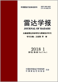
- Figure 1. The generating ways of terahertz wave
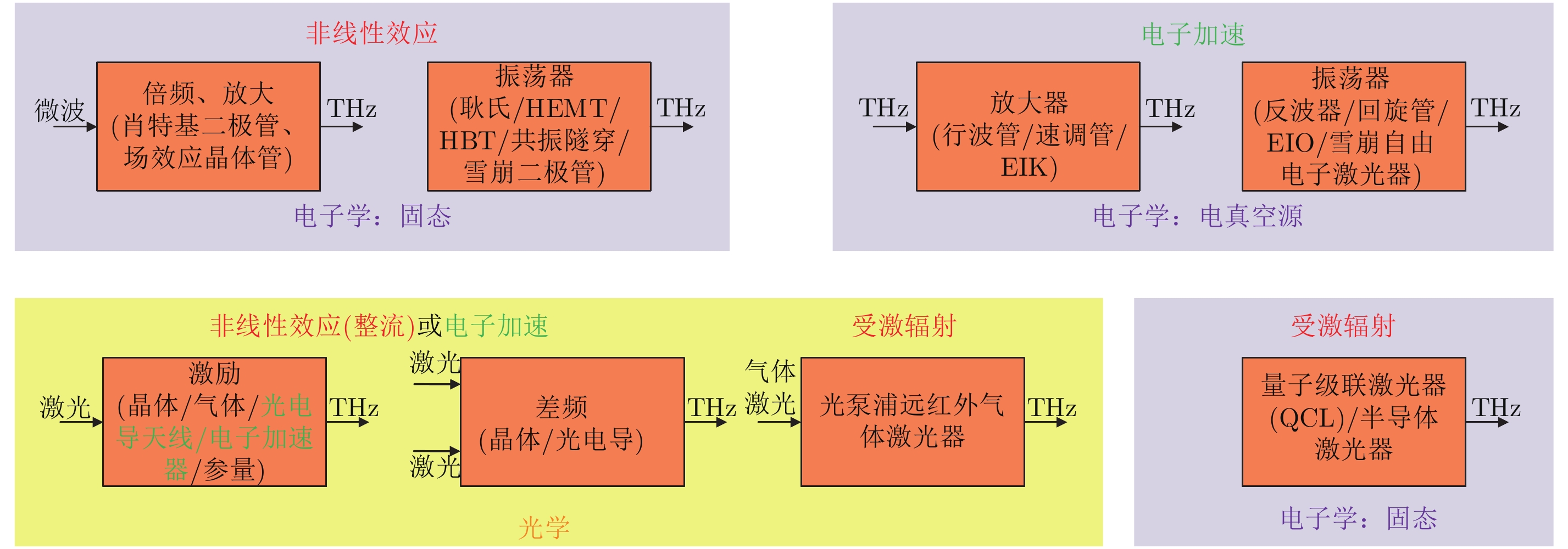
- Figure 2. The linear array scanning SAR
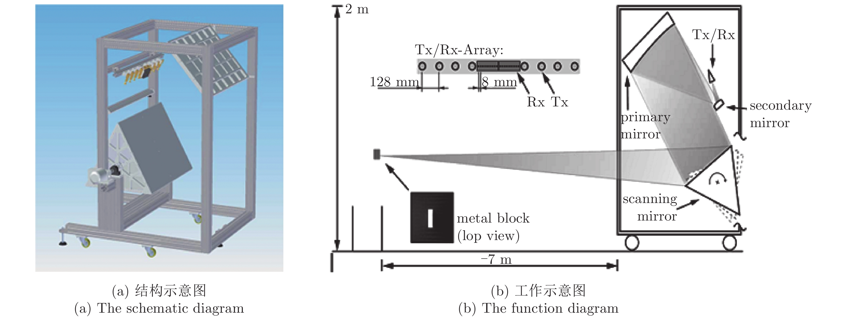
- Figure 3. The 225 GHz pulse radar and tracked result
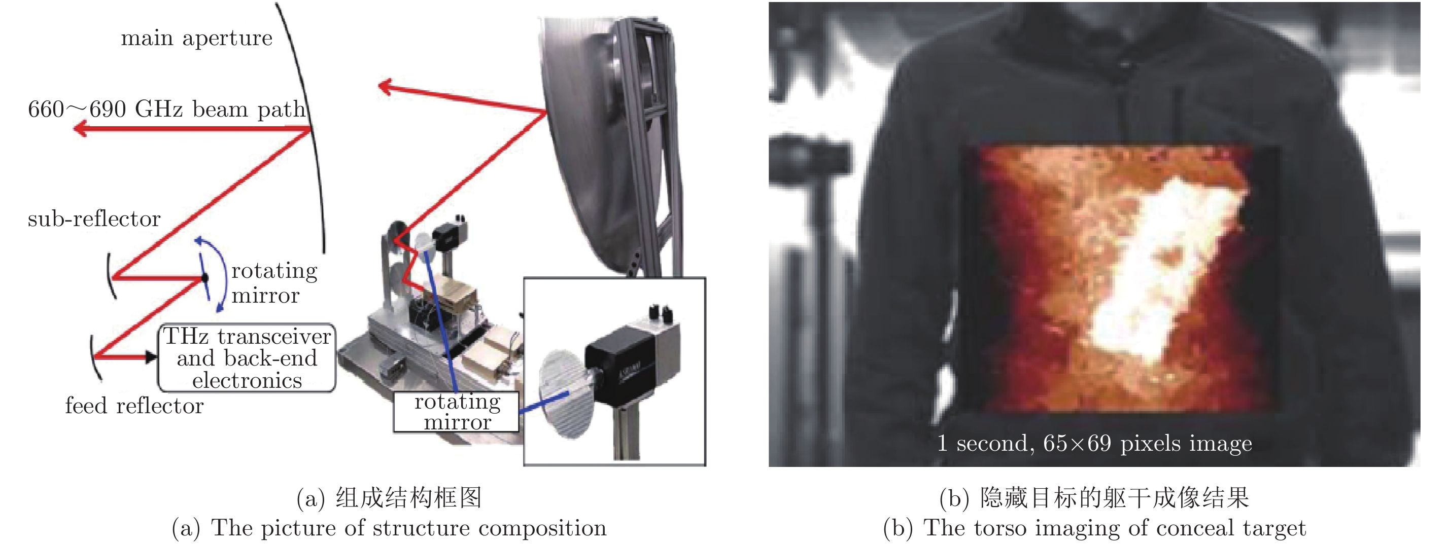
- Figure 4. The 670 GHz radar and the imaging result
- Figure 5. The terahertz radar on chip
- Figure 6. The 2.4 THz radar and the imaging result
- Figure 7. The developing process of terahertz radar
- Figure 8. The RCS comparing results of T5M3 and X-Patch
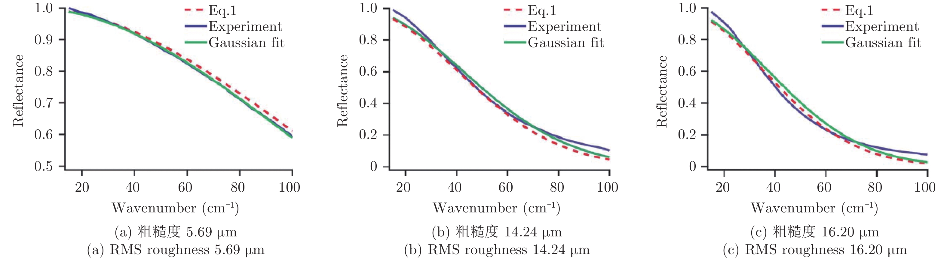
- Figure 9. The dissipation coefficient of three rough samples
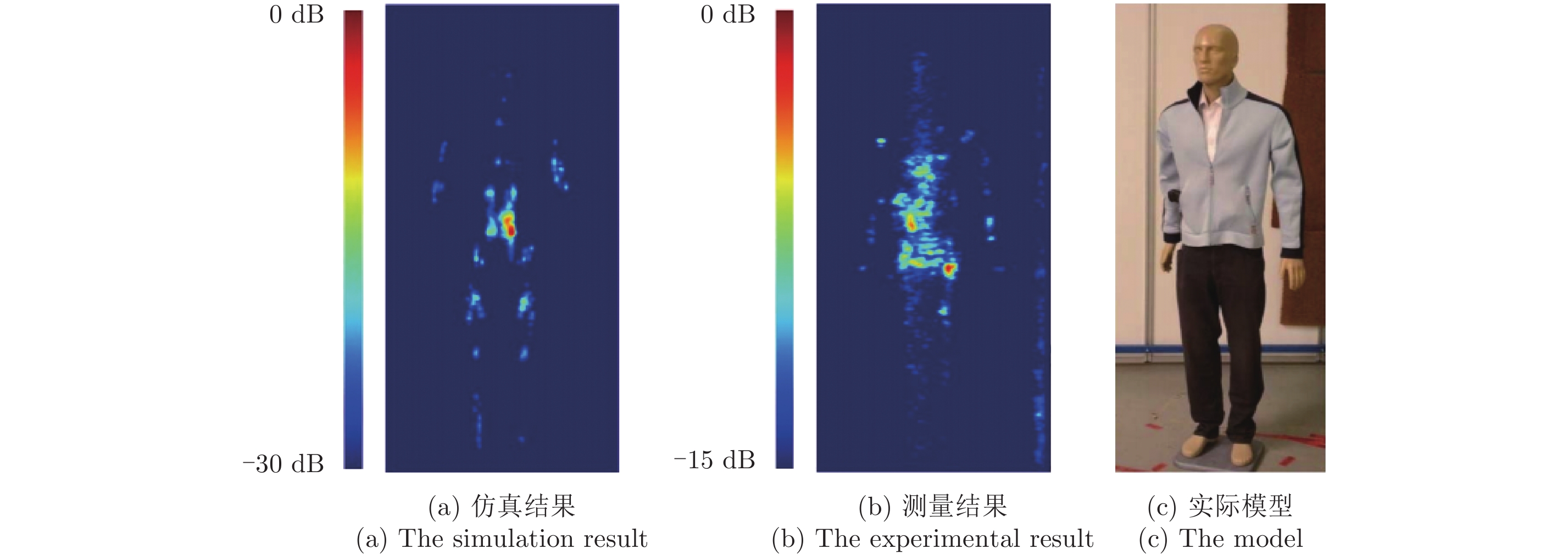
- Figure 10. The reconstructed image of the simulation and the experiment
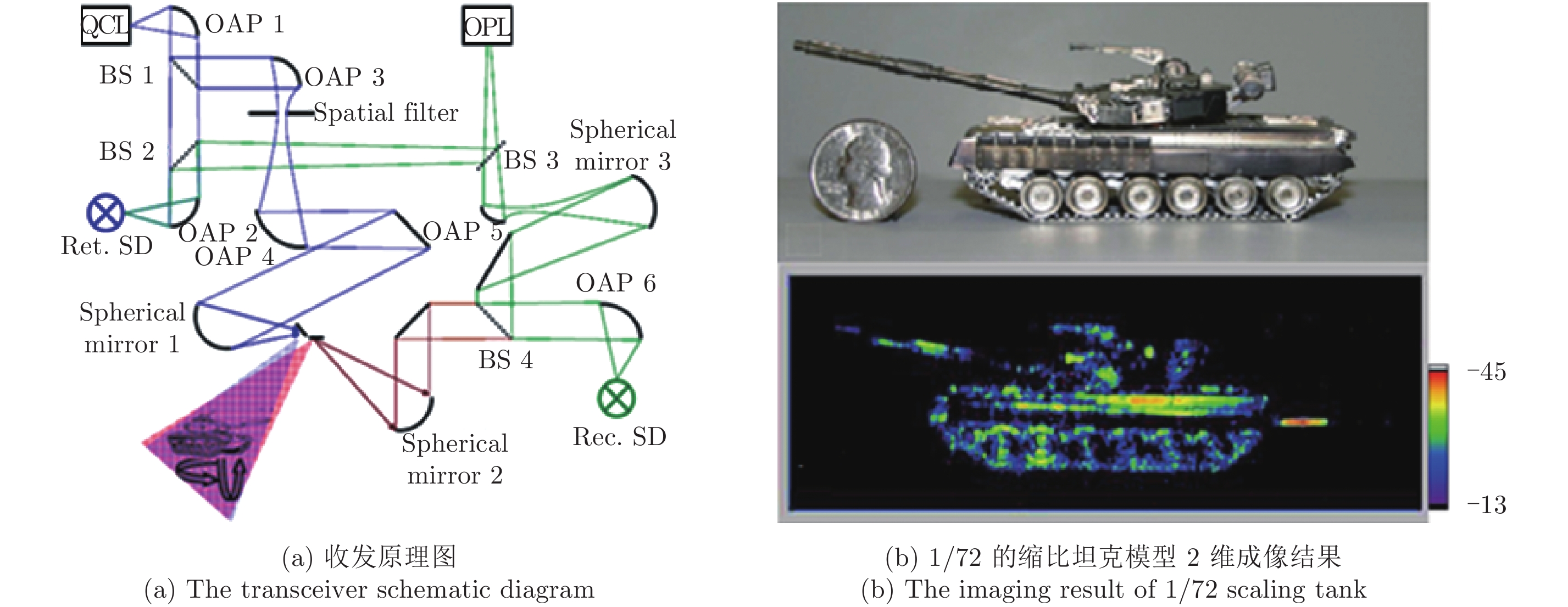
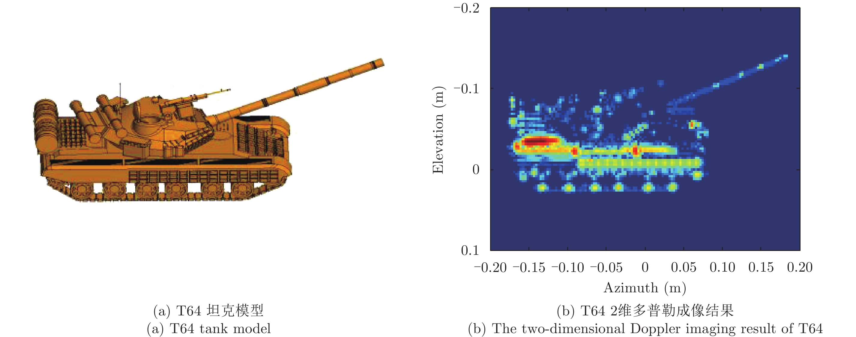
- Figure 11. The two-dimensional Doppler imaging of T64 based on 0.6 THz
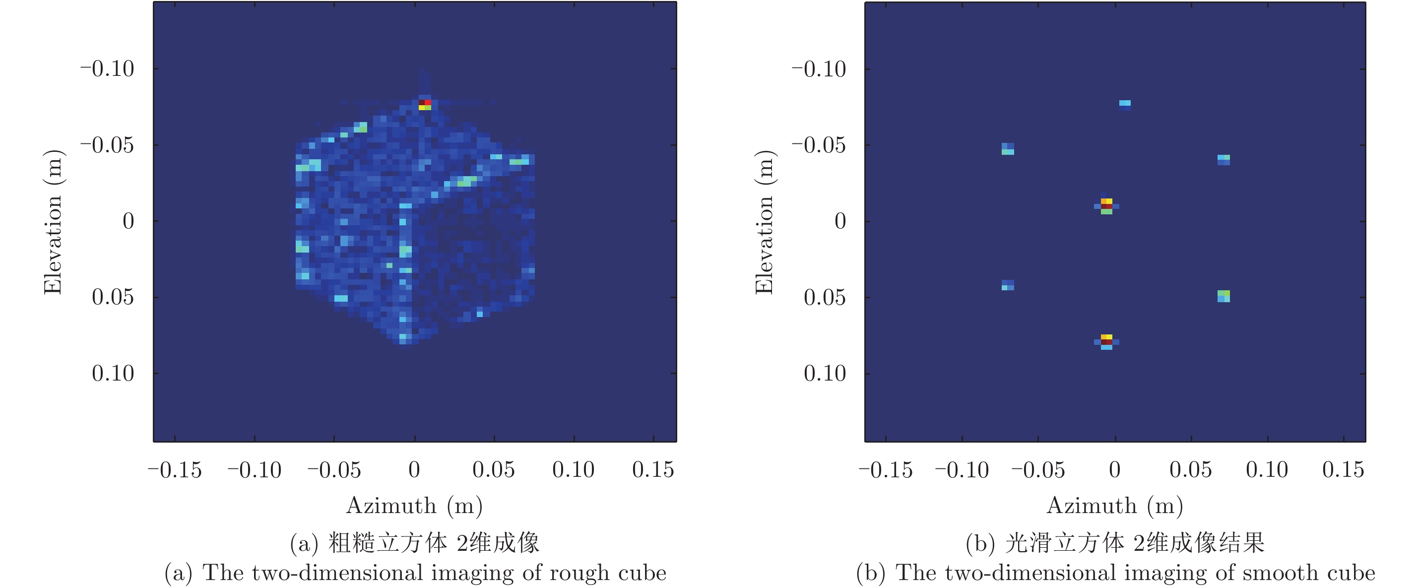
- Figure 12. The model and imaging of rough cube
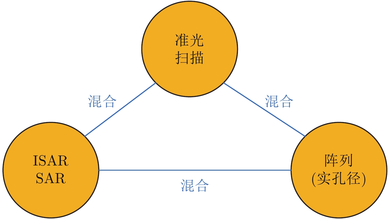
- Figure 13. The imaging ways of terahertz radar
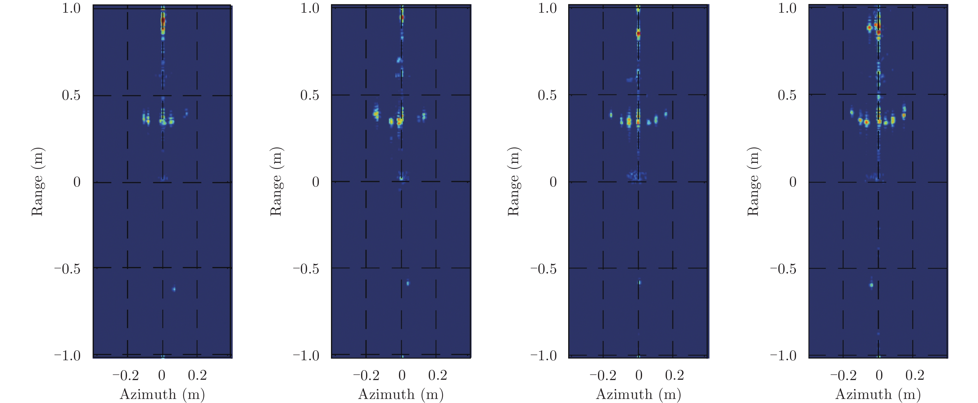
- Figure 14. The turntable imaging of bicycle with 140 m
- Figure 15. The imaging result of precession warhead
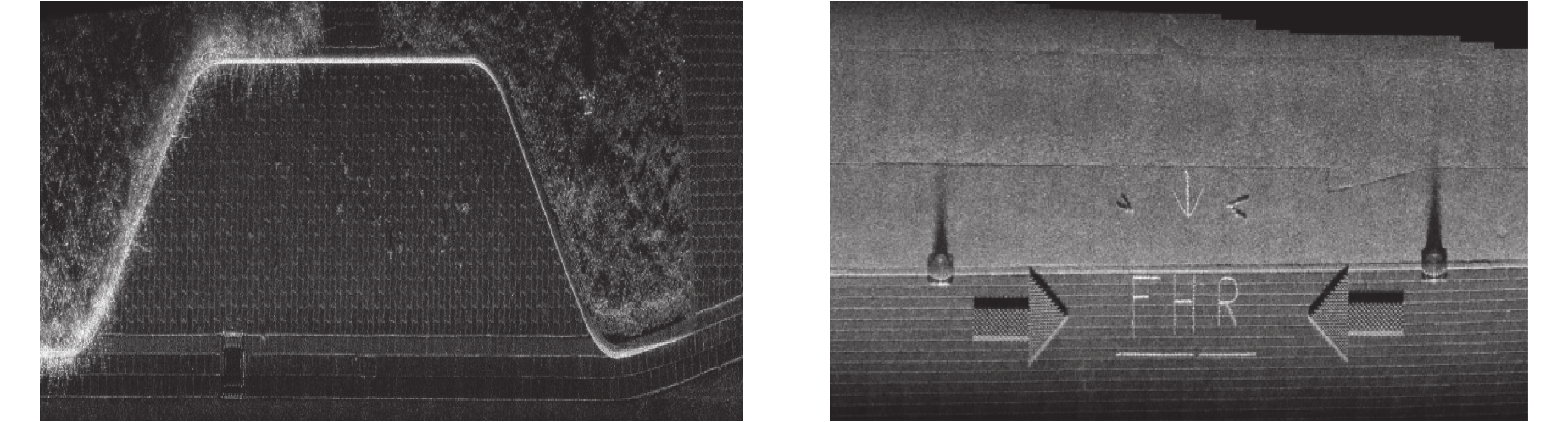
- Figure 16. The vehicle imaging of MIRANDA-300 radar
- Figure 17. The vehicle THz-SAR system and imaging of NUDT
- Figure 18. The intending array configuration of TeraSCREEN
- Figure 19. The imaging of the people carried pistol by 0.2 THz
- Figure 20. The picture and imaging of 340 GHz-MIMO of industrial institute
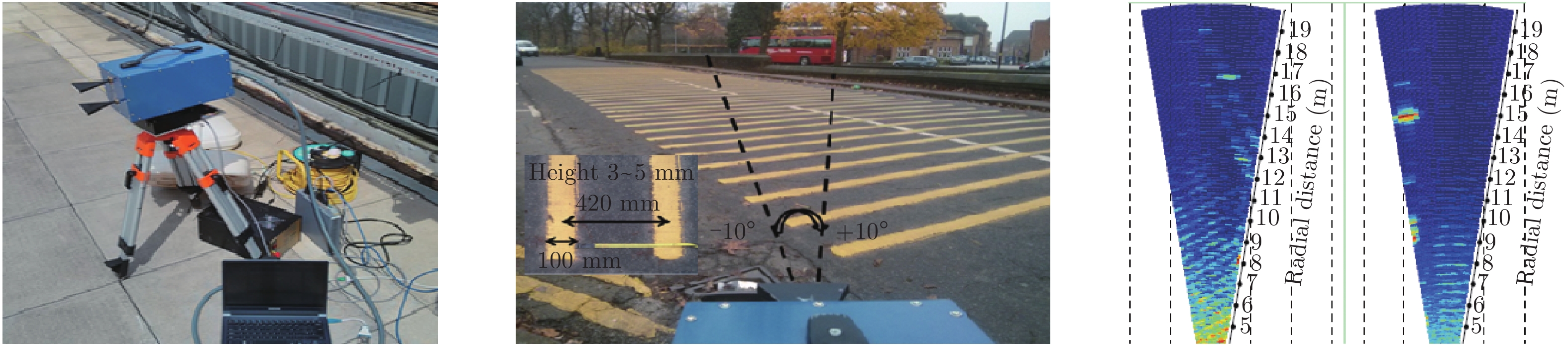
- Figure 21. The experimental system and result of University of Birmingham