
 Submit Manuscript
 Peer Review
 Editor Work
- Home
- Articles & Issues
-
Data
- Dataset of Radar Detecting Sea
- SAR Dataset
- SARGroundObjectsTypes
- SARMV3D
- AIRSAT Constellation SAR Land Cover Classification Dataset
- 3DRIED
- UWB-HA4D
- LLS-LFMCWR
- FAIR-CSAR
- MSAR
- SDD-SAR
- FUSAR
- SpaceborneSAR3Dimaging
- Sea-land Segmentation
- SAR Multi-domain Ship Detection Dataset
- SAR-Airport
- Hilly and mountainous farmland time-series SAR and ground quadrat dataset
- SAR images for interference detection and suppression
- HP-SAR Evaluation & Analytical Dataset
- GDHuiYan-ATRNet
- Multi-System Maritime Low Observable Target Dataset
- DatasetinthePaper
- DatasetintheCompetition
- Report
- Course
- About
- Publish
- Editorial Board
- Chinese
| Citation: | WANG Xinshuo, LU Jingyue, MENG Zhichao, et al. Forward-looking multi-channel synthetic aperture radar imaging and array attitude error compensation[J]. Journal of Radars, 2023, 12(6): 1155–1165. doi: 10.12000/JR23073

|
Forward-looking Multi-channel Synthetic Aperture Radar Imaging and Array Attitude Error Compensation
DOI: 10.12000/JR23073 CSTR: 32380.14.JR23073
More Information-
Abstract
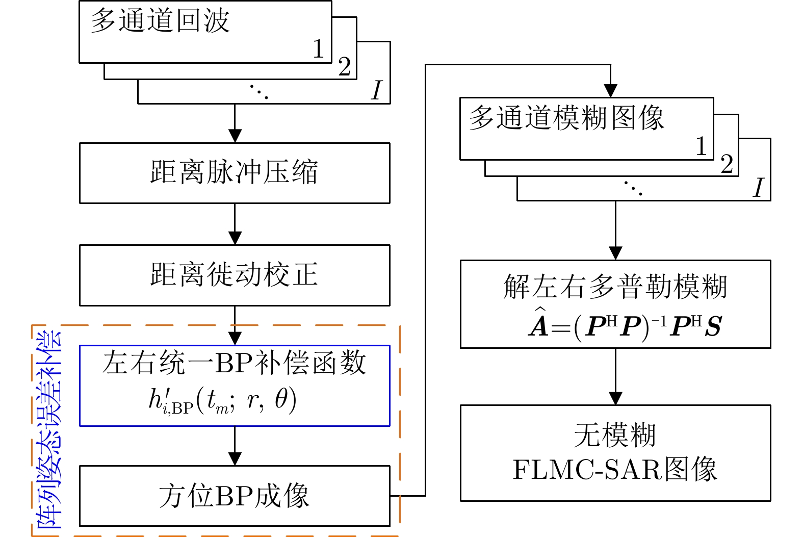
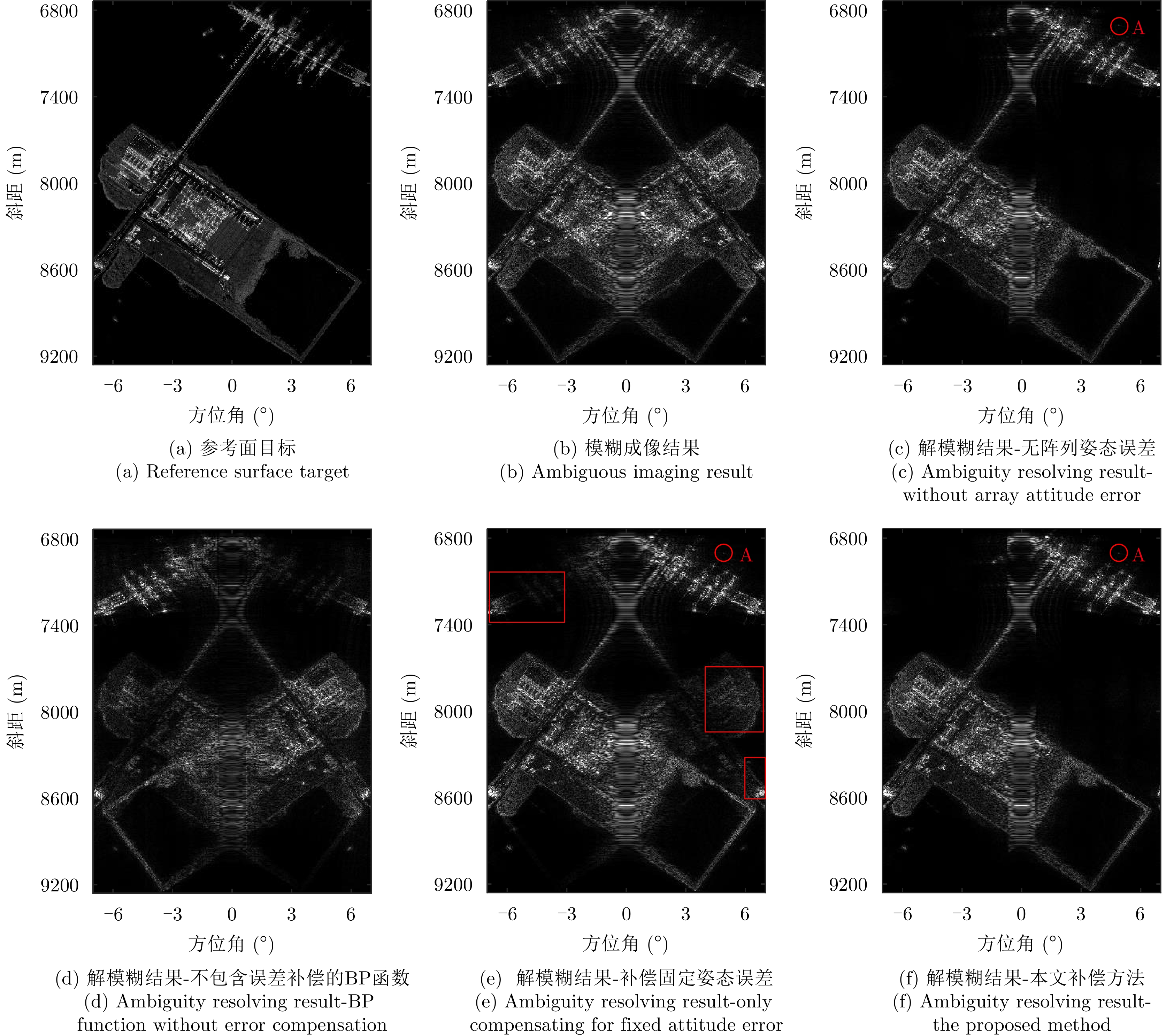
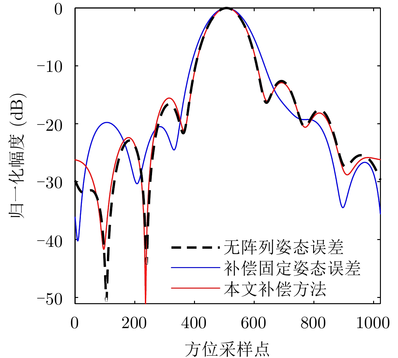
To solve the problem of left-right Doppler ambiguity in forward-looking Synthetic Aperture Radar (SAR) imaging, Forward-Looking Multi-Channel SAR (FLMC-SAR) can achieve Doppler ambiguity resolving imaging through beamforming. However, array deviation angle and time-varying platform attitude errors lead to the mismatch between the space and time characteristics of a target, which affects the Doppler ambiguity resolving imaging performance. This study proposes an FLMC-SAR imaging and array attitude error compensation method. First, the three-dimensional FLMC-SAR array deviation-angle error and time-varying platform attitude error models are established. The mechanism of matching the spatiotemporal characteristics of targets in the two-dimensional spatiotemporal spectrum plane is analyzed. In addition, a representation model is established to study the spatiotemporal characteristics mismatch caused by the array attitude error in the spatiotemporal plane. Thereafter, based on the non-left-right spatial variation of the error, we propose a method of adding an error compensation phase to the back projection function to uniformly compensate the array attitude error of left-right symmetric targets. The results of simulation experiments show that the proposed method can achieve FLMC-SAR array attitude correction and error compensation, enhance the performance of forward-looking Doppler ambiguity suppression, and ensure the azimuth resolution performance of forward-looking imaging. -

-
References
[1] KRIEGER G, MITTERMAYER J, BUCKREUSS S, et al. Sector imaging radar for enhanced vision[J]. Aerospace Science and Technology, 2003, 7(2): 147–158. doi: 10.1016/S1270-9638(02)01189-6[2] SONG Xuan, LI Yachao, ZHANG Tinghao, et al. Focusing high-maneuverability bistatic forward-looking SAR using extended azimuth nonlinear chirp scaling algorithm[J]. IEEE Transactions on Geoscience and Remote Sensing, 2022, 60: 5240814. doi: 10.1109/TGRS.2022.3228803[3] HU Ruizhi, RAO B S M R, MURTADA A, et al. Automotive squint-forward-looking SAR: High resolution and early warning[J]. IEEE Journal of Selected Topics in Signal Processing, 2021, 15(4): 904–912. doi: 10.1109/JSTSP.2021.3064175[4] SHAHREZAEI I H and KIM H C. A monostatic forward-looking staring spotlight SAR raw data generation and hybrid-domain image formation modifications based on extended azimuth nonlinear chirp scaling autofocusing[J]. IEEE Transactions on Aerospace and Electronic Systems, 2023, 59(3): 2329–2358. doi: 10.1109/TAES.2022.3212993[5] 卢景月, 张磊, 王冠勇. 前视多通道合成孔径雷达解模糊成像方法[J]. 电子与信息学报, 2018, 40(12): 2820–2825. doi: 10.11999/JEIT180177LU Jingyue, ZHANG Lei, and WANG Guanyong. Ambiguity resolving and imaging algorithm for multi-channel forward-looking synthetic aperture radar[J]. Journal of Electronics&Information Technology, 2018, 40(12): 2820–2825. doi: 10.11999/JEIT180177[6] LI Han, SUO Zhiyong, ZHENG Chengxin, et al. Study on airborne near-nadir TOPS SAR imaging with attitude angle error[J]. IEEE Transactions on Geoscience and Remote Sensing, 2022, 60: 5240012. doi: 10.1109/TGRS.2022.3226221[7] LU Jingyue, ZHANG Lei, HUANG Yan, et al. High-resolution forward-looking multichannel SAR imagery with array deviation angle calibration[J]. IEEE Transactions on Geoscience and Remote Sensing, 2020, 58(10): 6914–6928. doi: 10.1109/TGRS.2020.2977731[8] KLARE J, WEISS M, PETERS O, et al. ARTINO: A new high resolution 3D imaging radar system on an autonomous airborne platform[C]. 2006 IEEE International Symposium on Geoscience and Remote Sensing, Denver, USA, 2006: 3842–3845.[9] 杨泽民, 孙光才, 邢孟道, 等. 基于多通道联合自聚焦技术的机载三维SAR运动补偿[J]. 电子与信息学报, 2012, 34(7): 1581–1588. doi: 10.3724/SP.J.1146.2011.01365YANG Zemin, SUN Guangcai, XING Mengdao, et al. Motion compensation for airborne 3-D SAR based on joint multi-channel auto-focusing technology[J]. Journal of Electronics&Information Technology, 2012, 34(7): 1581–1588. doi: 10.3724/SP.J.1146.2011.01365[10] 丁振宇, 谭维贤, 王彦平, 等. 基于波数域子孔径的机载三维SAR偏航角运动误差补偿[J]. 雷达学报, 2015, 4(4): 467–473. doi: 10.12000/JR15016DING Zhenyu, TAN Weixian, WANG Yanping, et al. Yaw angle error compensation for airborne 3-D SAR based on wavenumber-domain subblock[J]. Journal of Radars, 2015, 4(4): 467–473. doi: 10.12000/JR15016[11] 孟智超. 前视多通道合成孔径雷达成像与抗干扰技术研究[D]. [硕士论文], 西安电子科技大学, 2021: 16–19.MENG Zhichao. Research on imaging and anti-interference of forward-look multichannel synthetic aperture radar[D]. [Master dissertation], Xidian University, 2021: 16–19.[12] 方振平, 陈万春, 张曙光. 航空飞行器飞行动力学[M]. 北京: 北京航空航天大学出版社, 2005: 20.FANG Zhenping, CHEN Wanchun, and ZHANG Shuguang. Flight Dynamics of Aero Vehicles[M]. Beijing: Beihang University Press, 2005: 20.[13] 保铮, 邢孟道, 王彤. 雷达成像技术[M]. 北京: 电子工业出版社, 2005: 139.BAO Zheng, XING Mengdao, and WANG Tong. Radar Imaging Technology[M]. Beijing: Publishing House of Electronics Industry, 2005: 139.[14] VILLANO M and KRIEGER G. Spectral-based estimation of the local azimuth ambiguity-to-signal ratio in SAR images[J]. IEEE Transactions on Geoscience and Remote Sensing, 2014, 52(5): 2304–2313. doi: 10.1109/TGRS.2013.2259244 -
Proportional views

- Publishing Ethics
- Journal Insights
- Abstracting & Indexing
- Peer Review Policies
- Guide for Authors
- Conference
- ISSN 2095-283X (Print)ISSN 2097-339X (Online)
- CN 10-1030/TN
- CODEN LXEUAO
About Journal
- Sponsor: China Radio Detection and Ranging Industry Association (CRIA)
- Phone: 010-58887062
- Email:radars@aircas.ac.cn
- Publisher: Leida Xuebao Bianjibu (Editorial office of the Journal of Radars)
Contacts Us

京ICP备20021838号-14
Supported by: Beijing Renhe Information Technology Co. Ltd

Export File
Citation
Format
Content
 DownLoad:
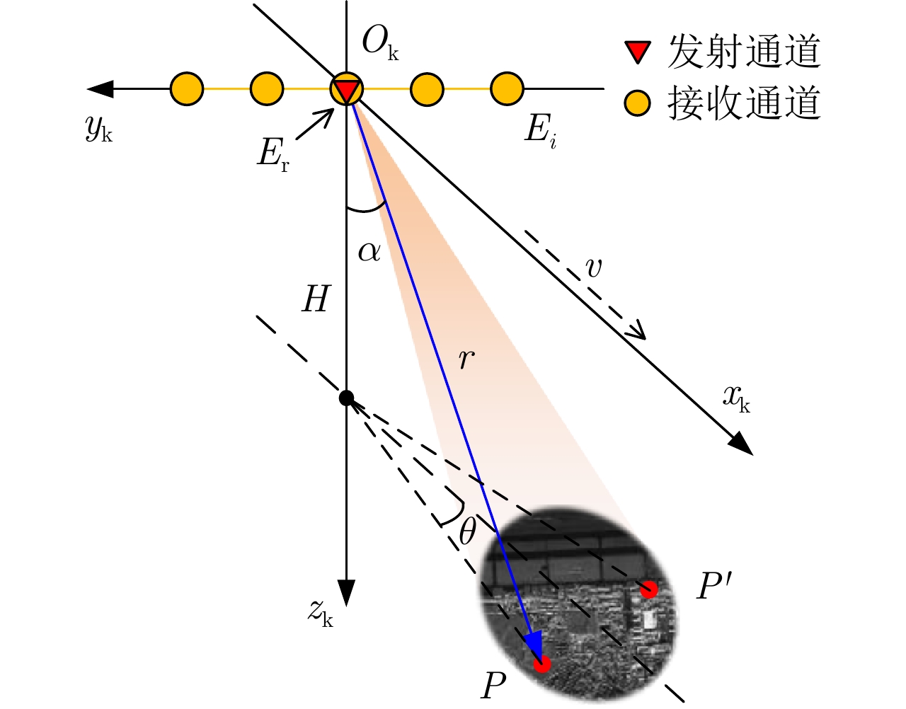
- Figure 1. FLMC-SAR imaging geometry
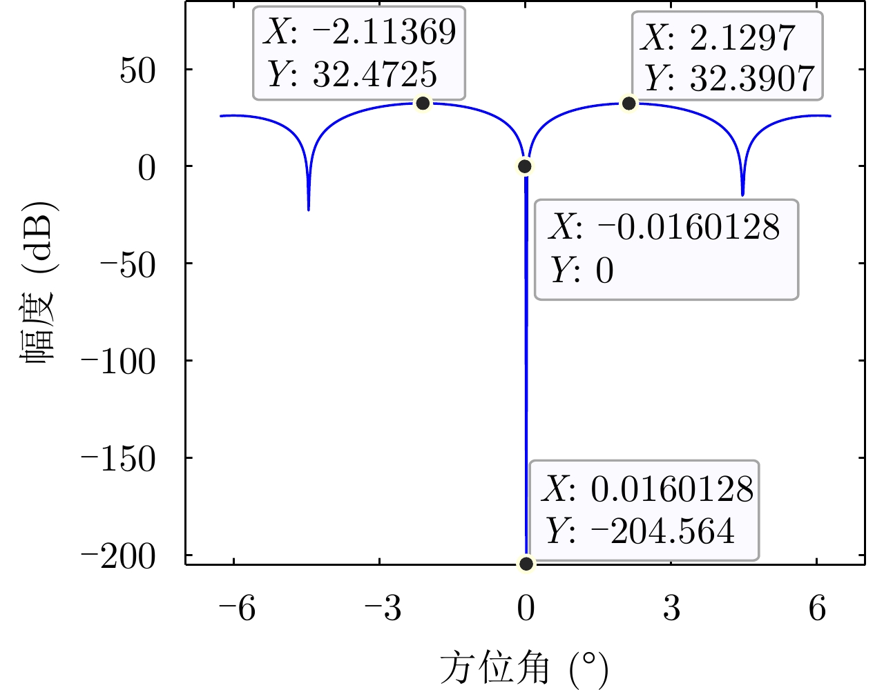
- Figure 2. Least squares beamforming pattern at small angles
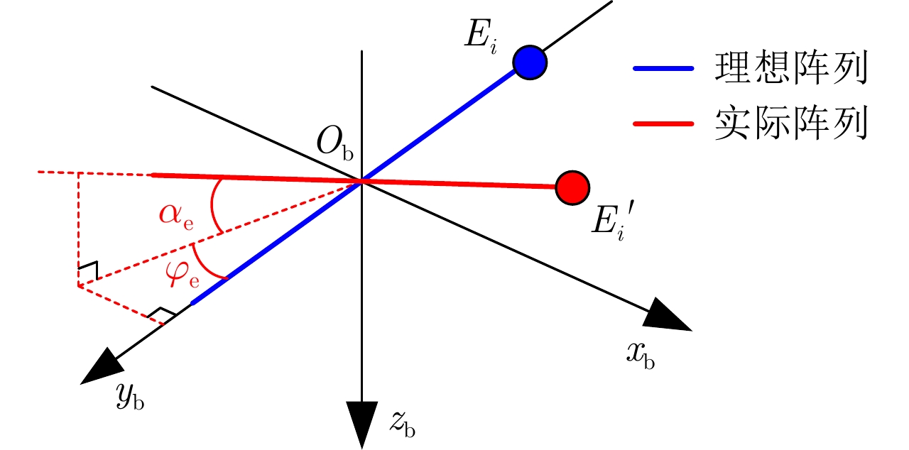
- Figure 3. Diagram of array deviation angle error
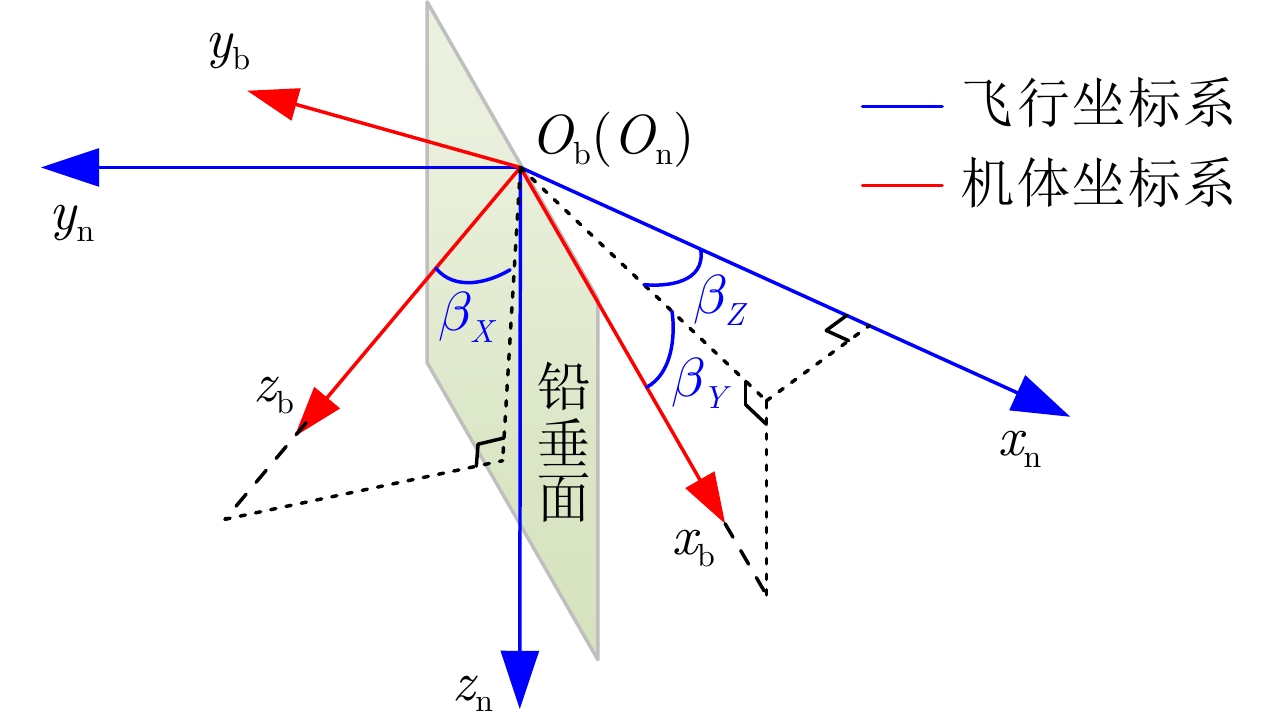
- Figure 4. Aircraft attitude angle
-
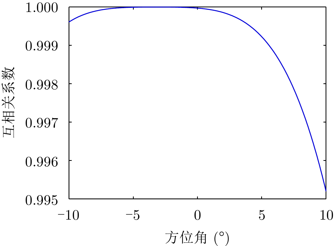
Figure 5. Cross correlation curve of steering vectors before and after using
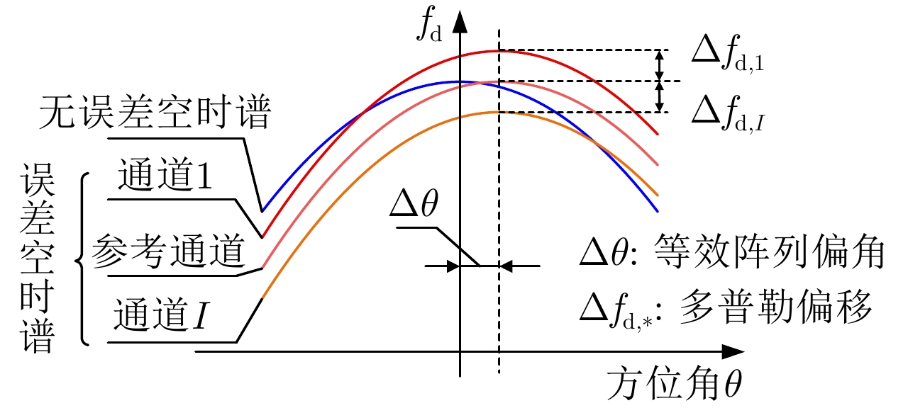
$\Delta \theta $ - Figure 6. Space-time characteristic mismatch caused by array attitude error
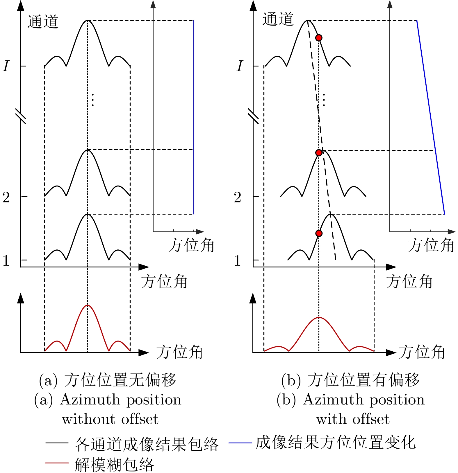
- Figure 7. The influence of azimuth position of ambiguous images on ambiguity resolving
- Figure 8. Flowchart of the proposed method
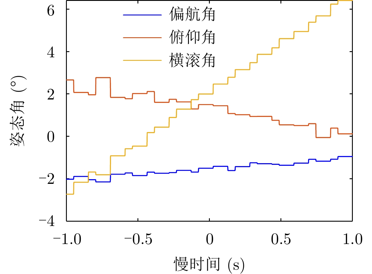
- Figure 9. Time-varying attitude angle
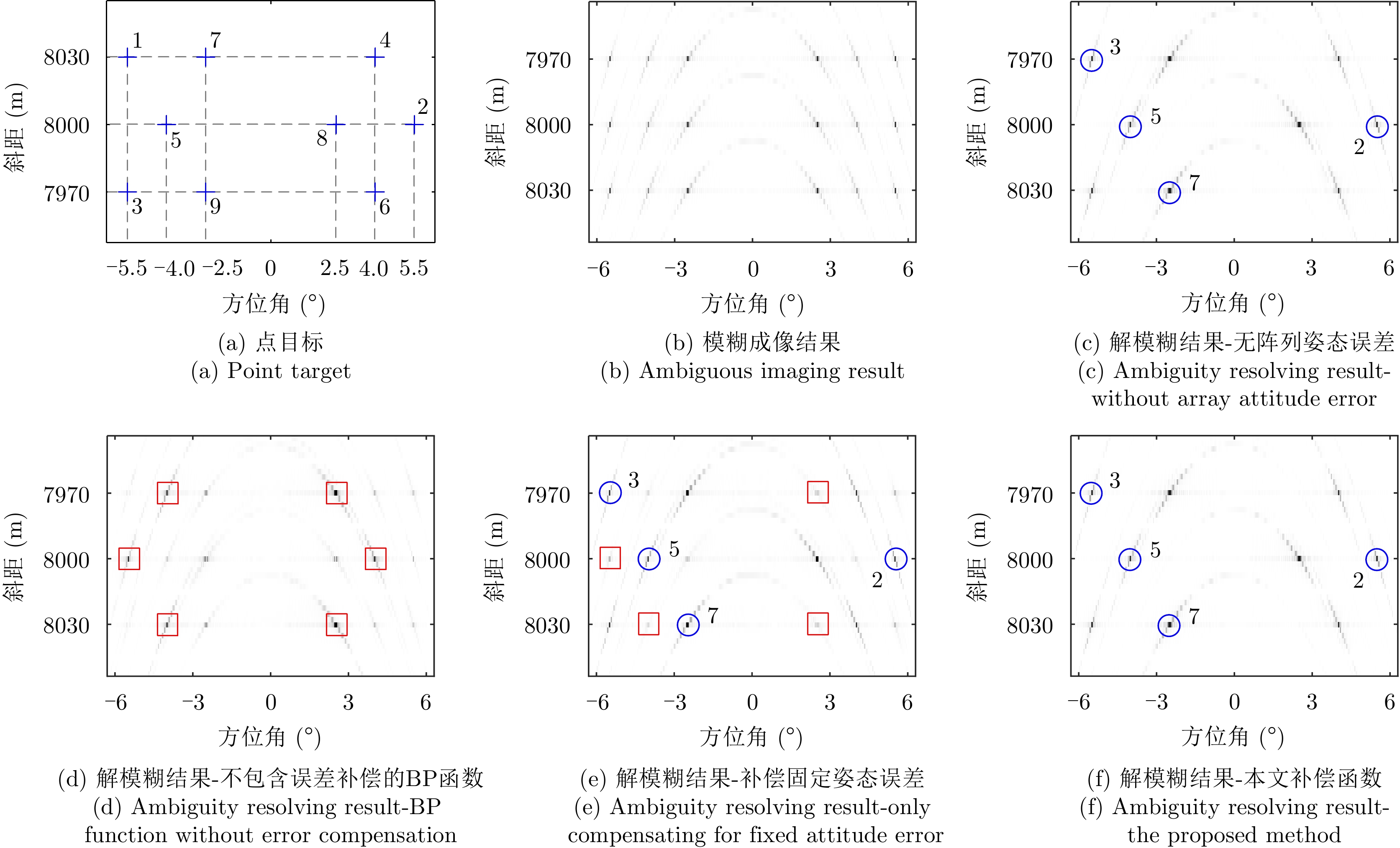
- Figure 10. Simulation results of the point targets
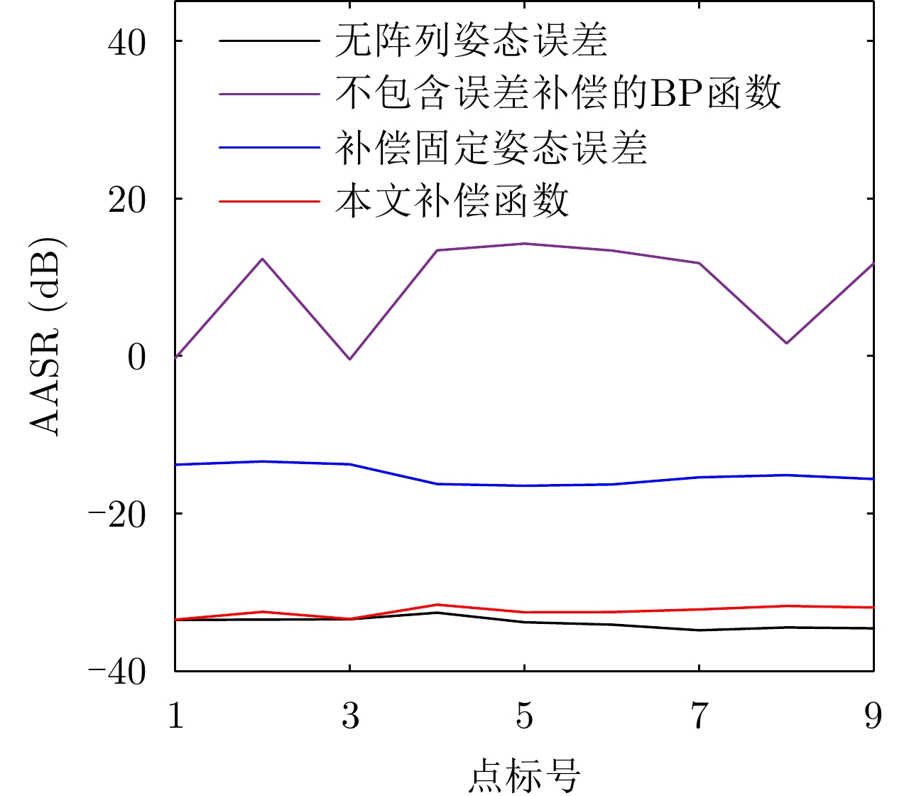
- Figure 11. Comparison of AASR
- Figure 12. Simulation results of the surface target
- Figure 13. Comparison of azimuth PSF at point A