The coprime array is an attractive technique of sparse array construction, which has gained researchers' intensive attentions over the past several years in the Direction-Of-Arrival (DOA) estimation, the MIMO communication, and so on. The coprime array has been demonstrated to be able to achieve O(MN) degree-of-freedoms with only O(M+N) sensors[1, 2]. An (M, N)-coprime array consists of two Uniform Linear subArrays (ULA): one is of M elements having inter-element spacing Nspacing Mλ/2, where M and N are chosen to be co- prime, λ is operational wavelength. It is worthy of noting that the inter-element spacing of coprime array is much larger than the half-wavelength typically required in conventional array configuration. For this reason, the coprime array is rather attractive in the sense of reducing mutual coupling between antenna elements. Additionally, there are situations that such half-wavelength minimum spacing is infeasible or impractical, for instance, the physical size of antenna sensors, such as many parabola antenna, is probably large than half-wavelength. Most recently, several helpful extensions of the original coprime array developed in Refs. [1, 2] have also been attempted, for instance, S. Qin et al. generalized the concept of coprime array with the use of two strategies: one is the compression of the inter-element of spacing of one constituting subarray, and the other is the displacement of two subarrays[3]. As such, one can get the flexibility of trading-off between unique lags and consecutive lags for DOA estimation while keeping a larger minimum inter-element spacing as large as possible. Tan et al. incorporated more advanced algorithm of sparse reconstruction into coprime array technique together, which leads to important improved perfor- mances in the aspects of DOA estimation accuracy, resolution ability, and others[4, 5].
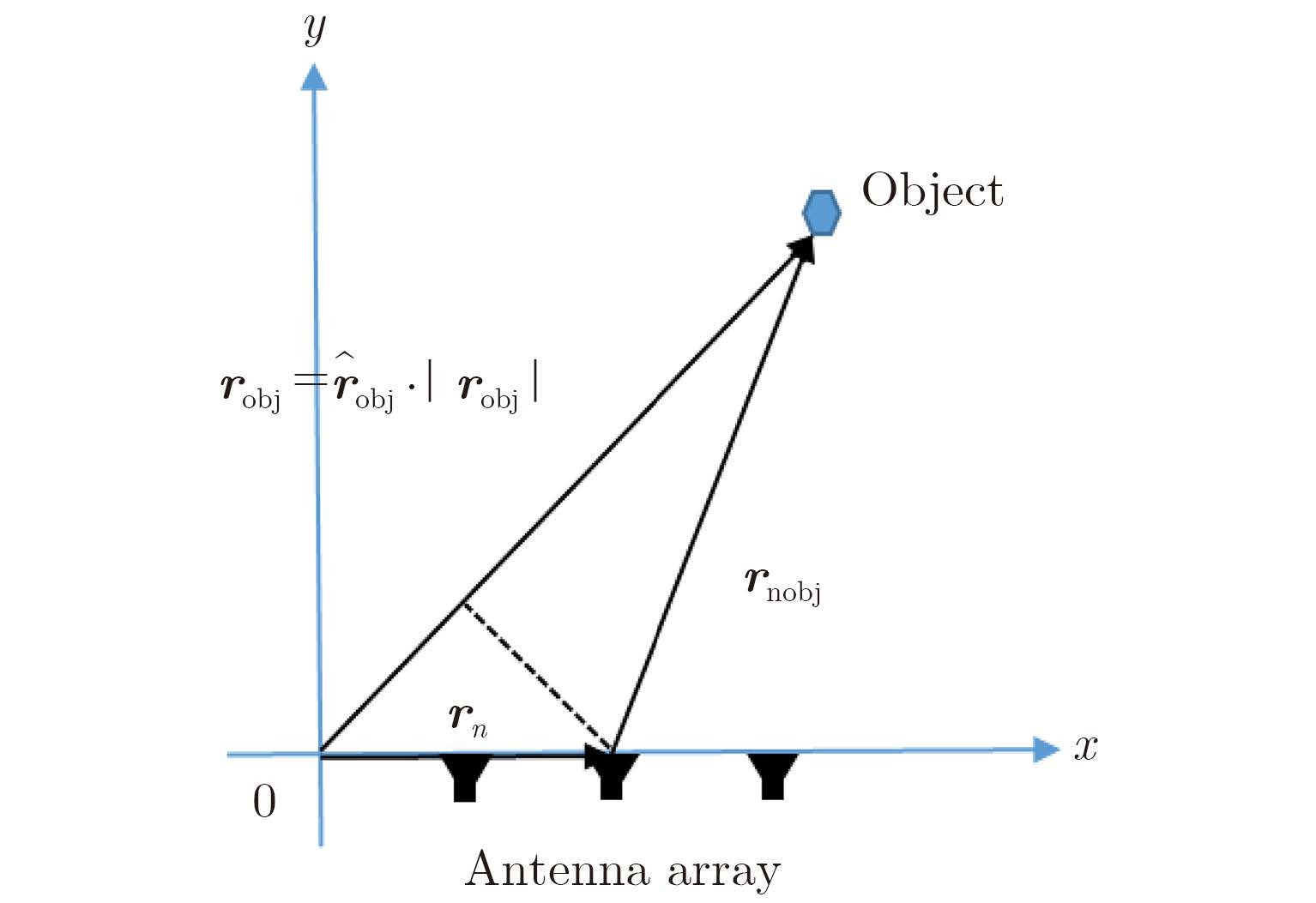
To our best knowledge, the coprime array approaches reported in literatures so far relystrongly on the far-field approximation, which requires the probed object to be sufficiently far from sensors. In this sense, such theories fail to deal with the problem of short-range radar detection since probed object are nearby sensors. To provide more clear insights into this point, we make following arguments. Referring to Fig. 1, the Three-Dimensional (3D) scalar Green's function of $g\left( {{r_{{\rm{obj}}}},{r_n}} \right) = \frac{{{{\rm{e}}^{i{k_0}\left| {{r_{{\rm{obj}}}} - {r_n}} \right|}}}}{{4{\rm{\pi }}\left| {{r_{{\rm{obj}}}} - {r_n}} \right|}}$ is applied to describe the system response at robj arising from a dipole antenna located at rn. The far-field approximation is conventionally characterized by $\left| {{{{r}}_{\rm{obj}}}} \right| \gg {{{r}}_n} \bullet {\hat {{r}}_{\rm{obj}}}$, and $\left| {{{{r}}_{\rm{obj}}}} \right|$ is the distance from coordinate center to targets, and ${\hat {{r}}_{\rm{obj}}}$ is the unit direction vector from coordinate center to targets. With such assumption, the Green's function is approximated to be of $\frac{{{{\rm{e}}^{i{k_0}\left| {{r_{{\rm{obj}}}} - {r_n}} \right|}}}}{{4{\rm{\pi }}\left| {{r_{{\rm{obj}}}} - {r_n}} \right|}} \approx \frac{{{{\rm{e}}^{{\rm{j}}{k_0}\left( {\left| {{r_{{\rm{obj}}}}} \right| - {r_n} \bullet {{\hat r}_{{\rm{obj}}}}} \right)}}}}{{4{\rm{\pi }}\left| {{r_{{\rm{obj}}}}} \right|}}$, which is the basis of the theory of standard coprime array, however, can be justified only when the distance between probed objects and antenna is much larger than 10λ.
|
Fig.1 The illustrated map of far-field approximation |
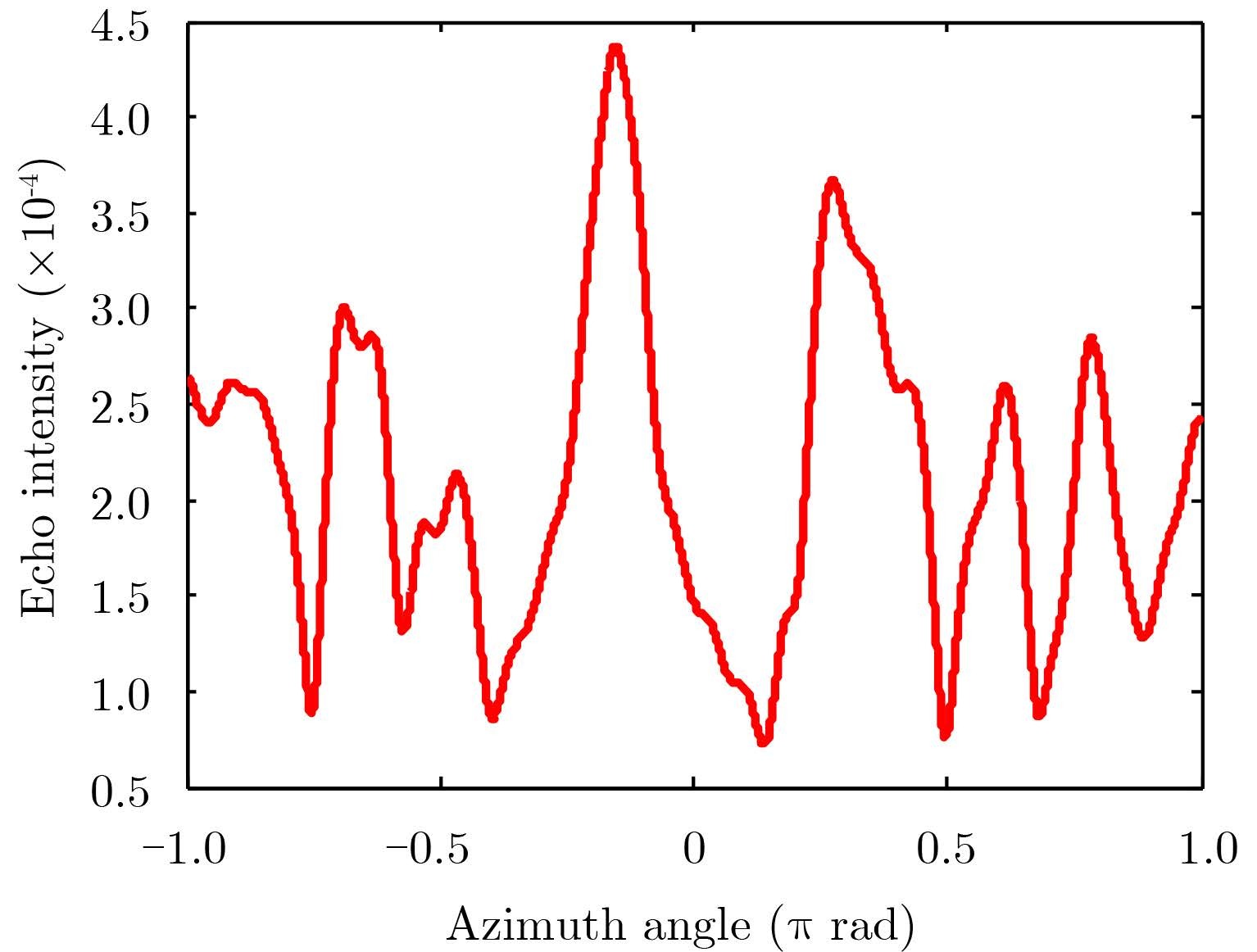
For the purpose of short-range imaging, above far-field approximation cannot be satisfied since the distance between probed objects and antennas is usually smaller than 10λ, which brings significant error for locating the objects under investigation. To show this point, a numerical simulation is implemented and its corresponding result achieved by running the strategy of traditional coprime array is shown in Fig. 2, where one near-field point target is located at (0, λ).
|
Fig.2 The result achieved by using the standard coprime array developed in Ref. [1], where the probed object is a point target located at (0, λ) and λ=1 m. The x-axis corresponds to the azimuth angle ranging within (-π, π) rad, while y-axis denotesecho intensity |
This paper investigates the capability of coprime array for the short-range radar sensing, where the object under investigation is NOT far from sensors (either the transmitter or receiver). We demonstrate that the (M, N)-coprime array configuration suffices to retrieve the object spectrum over $\left[{ - 2{ \tau } {k_0}, 2{ \tau } {k_0}} \right]$ with the resolution of $4{\rm{{ \tau } }}{k_0}/MN$ where k0 denotes free space wavenumber, and τ is a factor. As a consequence, the (M, N)-coprime array allows for resolving O(M, N) objects in the near-field of sensors with the spatial resolution of $\lambda /4\tau$. Furthermore, the performance of the coprime array for dealing with Through-Wall-Imaging (TWI) problem has also been studied[6].
The rest of this paper is organized as follows. A brief overview of standard co-prime array is made in Subsection 2.1, followed by presenting our methodology of coprime array for the problem of short-range radar detection in Subsection 2.2. Afterwards, the performance of proposed methodology for the TWI application is investigated in Subsection 2.3. Section 3 presents a selected number of numerical simulations to demonstrate the usefulness of proposed methodology. Finally, some conclusions are summarized in Section 4.
2 Problem Statement and Proposed MethodologyThis section is devoted to present the operational principal of the (M, N)-coprime array for resolving the problem of short-range radar imaging. To proceed our discussion, the basic concepts of co-prime array is briefly overviewed for following comparison.
2.1 Basic properties of P. P. Vaidyanathan and P. Pal’s coprime array[1]Following notations adopted in Ref. [1], the (M, N)-coprime array consists of a coprime pair of ULAs, where one is of M sensors with an inter-element spacing of Nλ/2, whereas the other is of N elements with an inter-element spacing of Mλ/2. For the purpose of active coprime sensing, one of two constituting subarrays of (M, N)-coprime array configuration is used for the purpose of transmitting signal, and the other is for receiving signal. The transmitting array with M taps h(n) has a beam pattern (or called antenna pattern):
| $H\left( { \omega } \right) = \mathop \sum \limits_{n = 0}^{M - 1} h\left( n \right){{\rm{e}}^{ - {\rm{j}}{ \alpha } n}}$ | (1) |
where α=2πdsinθ/λ, and ω=πsinθ. Taking the inter-element spacing denoted by d to be d=Nλ/2, the resulting beam pattern becomes:
| $H\left( {{{\rm{e}}^{{\rm{j}}\omega N}}} \right) = \sum\limits_{n = 0}^{M - 1} h \left( n \right){{\rm{e}}^{ - {\rm{j}}N\omega n}}$ | (2) |
Assuming that H(ω) is ideal low-pass, specifically,
| $H\left( {{{\rm{e}}^{{\rm{j}}\omega }}} \right) = \left\{ \begin{array}{l} 1,\left| \omega \right| < {\rm{\pi }}/M\\ 0,{\rm{otherwise}} \end{array} \right.$ | (3) |
Then Eqs.(2) and (3) imply that $H\left( {{{\rm{e}}^{{\rm{j}}\omega N}}} \right)$would have N passbands, with each passband having width of 2π/MN. Similarly, for the receiving array with N taps g(n), its associated beam pattern $G\left( {{{\rm{e}}^{{\rm{j}}\omega M}}} \right)$ would have M passbands with width 2π/MN, where G(ω) is defined by Eq. (4), i.e.,
| $G\left( {{{\rm{e}}^{{\rm{j}}\omega }}} \right) = \left\{ \begin{array}{l} 1,\left| \omega \right|\frac{{\rm{\pi }}}{N}\\ \begin{array}{*{20}{c}} {0,}&{{\rm{otherwise}}} \end{array} \end{array} \right.$ | (4) |
Introducing two sets of array-banks:
| ${\rm{}}{H_k}\left( z \right) = H\left( {{z^N}W_M^k} \right) = \mathop \sum \limits_{m = 0}^{M - 1} h\left( m \right){z^{ - mN}}W_M^{ - mk}$ | (5a) |
and
| ${G_l}\left( z \right) = G\left( {{z^M}W_N^l} \right) = \mathop \sum \limits_{n = 0}^{N - 1} g\left( n \right){z^{ - nM}}W_N^{ - nl}$ | (5b) |
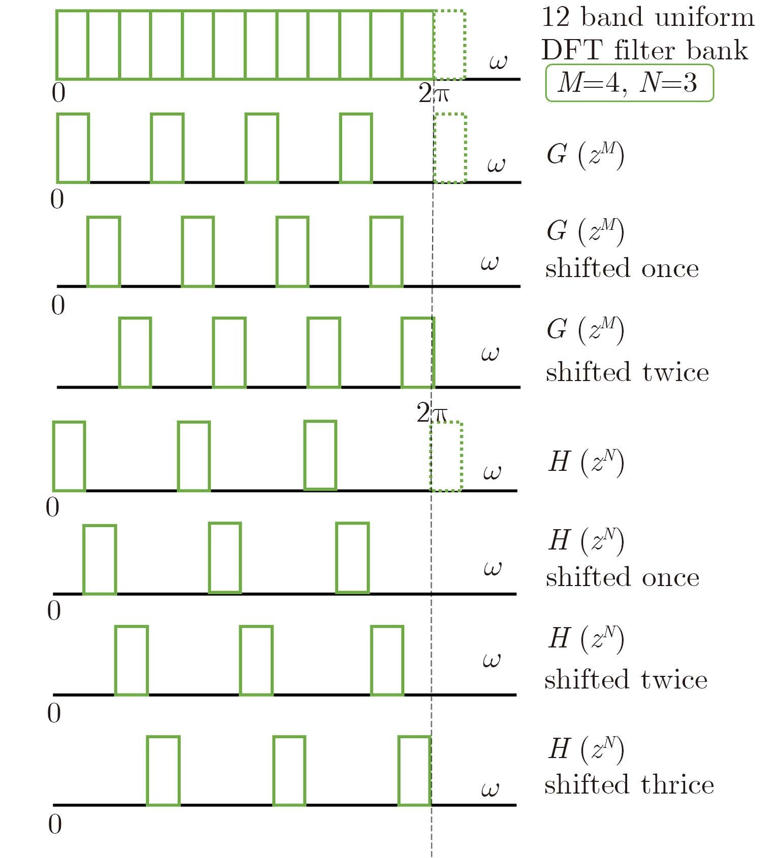
where 0≤k≤M-1, 0≤l≤N-1 and z=ejω. As illustrated in Fig. 3, the set of filters Hk(z) (or, resp. ${G_l}\left( z \right)$) are shifted versions of $H\left( {{{\rm{e}}^{{\rm{j}}\omega N}}} \right)$(or, resp., $G\left( {{{\rm{e}}^{{\rm{j}}\omega M}}} \right)$ in increment of 2π/MN. Furthermore, one can immediately deduce the product of the k-th and l-th steered array patterns of $H\left( {{z^N}W_M^k} \right)$ and $G\left( {{z^M}W_N^l} \right)$ as:
|
Fig.3 Hk(Z) and Gl(Z) are shifted versions of H(ejωH) and G(ejωM) in increment of 2π/MN, respectively. Here, M=4 italic>and N=3 are considered[1] |
| ${F_{lk}}\left( {{{\rm{e}}^{{\rm{j}}\omega }}} \right) = H\left( {{{\rm{e}}^{{\rm{j}}\omega N}}W_M^k} \right) \cdot G\left( {{{\rm{e}}^{{\rm{j}}\omega M}}W_N^l} \right)$ | (6) |
where $0 \le k \le M - 1$, $0 \le l \le N - 1$. From Eq. (6) it can be observed that the response ${F_{lk}}\left( {{{\rm{e}}^{{\rm{j}}\omega }}} \right)$ has only one overlapping passband centered at 2πi/MN, with bandwidth of 2π/MN, which implies that the set of MN radar responses ${F_{lk}}\left( {{{\rm{e}}^{{\rm{j}}\omega }}} \right)$ can be utilized to localize the probed object. Moreover, we could identify O(MN) objects with the use of onlyM+N–1 sensors.
Note that above conclusion relies on the assumption of ideal low-pass filter, as demonstrated by Eqs. (3) and (4). However, this kind of filter is obviously infeasible in practice. To bypass this issue, a little bit more sensors are utilized[1]. To characterized this issue mathematically, a scenario-dependent factor denoted by τ is introduced, in particular,
| $\tau = \frac{{{\text{Number of antennas used ideally by Eqs}}.(3){\text{or(4)}}}}{{{\text{Number of antennas used actually}}}}$ |
where $\tau$ is decided by angle $\theta$ of target and antennas, which will be detailed below.
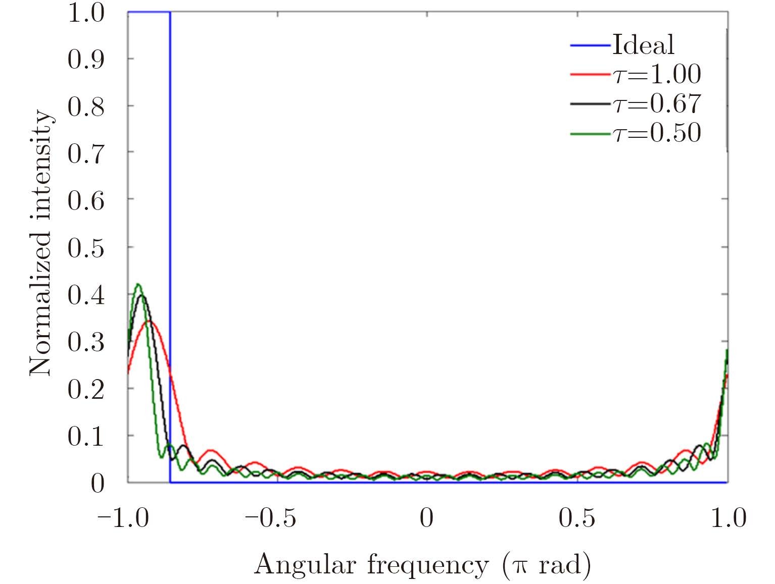
To numerically demonstrate this argument, we conducted a set of simple simulations, where M=9 and N=7 are used. From Fig. 4 we can notice that the bandwidth of constructed filter (denoted by red line) is greater than the ideal one, which implies that more sensors, correspondingly, $\tau$=0.64 and 0.5, are required to achieve the desirable resolution.
|
Fig.4 The blue curve stands for the ideal filter when M=9 and N=7. The red curve corresponds to the filter designed with $\tau$=1 (M=9 and N=7). In addition, the filters with $\tau$=0.64 (M=14 and N=11) and $\tau$=0.5 (M=18 and N=14) are denoted by the black and green curve, respectively |
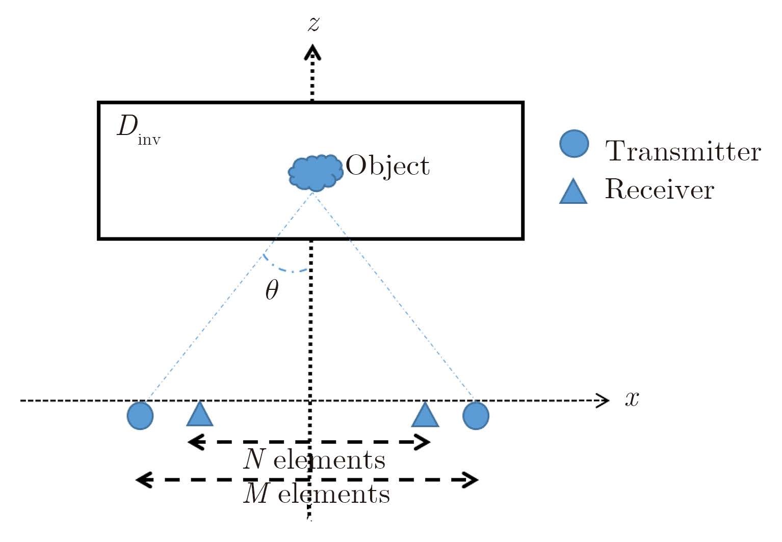
In this subsection, we turn to the discussion of the performance of coprime array for short-range detection. For the purpose of illustrating operational principle, we restrict the discussion within Two-Dimensional (2D) case where targets are assumed to be infinitely long and invariance along the y-axis.With reference to Fig. 5, the coprime array configuration is set as follows: M transmitters and N receivers are uniformly distributed with the intervals of Nλ/4τ and Mλ/4τ, respectively, along the line z=0. The probed object falls into the investigation domain denoted by Dinv, and f means working frequency.
|
Fig.5 The structure is demonstrated with the background medium being free space. θ is denoted as the angle of targets and antennas |
As pointed out previously, the theory of coprime array in literatures relies on the far-field assumption, as implied in Eq. (1). Apparently, such theory should be modified for the short-range scenario. For this purpose, instead of Eq. (1), the beam pattern arising from an M-elements ULA can be formulated as:
| ${{E}}\left( {{r}} \right) = \mathop \sum \limits_m g\left( {{{r}}, {{{r}}_m}} \right) \bullet h\left( m \right)$ | (7) |
Herein r=(x, z) denotes the position of probed target, r=(xm, 0) is the position of the m-th antenna, where ${x_m} = \frac{{\left( {m - 1} \right)N\lambda }}{{4{ \tau } }} - \frac{{\left( {M - 1} \right)N\lambda }}{{8{ \tau } }}$ and τ=sinθ. In addition, g(r, rm) is 2D free-space Green's function, and has following spectral representation[7], i.e.,
| \[\begin{array}{l} g\left( {r,{r_m}} \right) = \frac{i}{4}H_0^{\left( 1 \right)}\left( {{k_0}\left| {r - {r_m}} \right|} \right)\,\\ = \frac{i}{4}\frac{1}{\pi }\int_{ - \infty }^{ + \infty } {\rm{d}} {k_x}\frac{{{{\rm{e}}^{i{k_x}\left( {x - {x_m}} \right)}}}}{{{k_z}}}{{\rm{e}}^{i{k_z}\left( {z - 0} \right)}}\,\\ \approx \frac{i}{4}\frac{1}{\pi }\int_{ - 2\tau {k_0}}^{2\tau {k_0}} {\rm{d}} {k_x}\frac{{{{\rm{e}}^{i{k_x}\left( {x - {x_m}} \right)}}}}{{{k_z}}}{{\rm{e}}^{i{k_z}z}} \end{array}\] | (8) |
where $H_0^{\left( 1 \right)}\left( \cdot \right)$ denotes the first-kind zero-th order Hankel function. Using Eq. (8) in Eq. (7) leads to
| $\begin{aligned} {{E}}\left( {{r}} \right) = & \mathop \sum \limits_m \frac{i}{4}\frac{1}{\pi }\int_{ - 2\tau {k_0}}^{2\tau {k_0}} {\rm{d}}{k_x}h\left( {{x_m}} \right)\frac{{{{\rm{e}}^{i{k_x}\left( {x - {x_m}} \right)}}}}{{{k_z}}}{{\rm{e}}^{i{k_z}z}}\\ = & \frac{i}{4}\frac{1}{\pi }\int_{ - 2\tau {k_0}}^{2\tau {k_0}} {\rm{d}}{k_x}\frac{{{{\rm{e}}^{i{k_x}x}}}}{{{k_z}}}{{\rm{e}}^{i{k_z}z}}\mathop \sum \limits_m h\left( {{x_m}} \right){{\rm{e}}^{ - i{k_x}{x_m}}}\\ = & \frac{i}{4}\frac{1}{\pi }\int_{ - 2\tau {k_0}}^{2\tau {k_0}} {\rm{d}}{k_x}\frac{{{{\rm{e}}^{i{k_x}x}}}}{{{k_z}}}{{\rm{e}}^{i{k_z}z}}\tilde h\left( {N{k_x}} \right) \end{aligned}$ | (9) |
where $\tilde h\left( {N{k_x}} \right) = \sum\nolimits_m {h\left( {{x_m}} \right){{\rm{e}}^{ - i{k_x}{x_m}}}} $ means the Fourier transform of h(xm) with respect to xm. As done for standard coprime array, $\tilde h\left( {{k_x}} \right)$ is assumed to be ideal low-pass, namely,
| $\tilde h\left( {{k_x}} \right) = \left\{ {\begin{array}{*{20}{c}} {1, }&{\left| {{k_x}} \right| \le 2{k_0}\tau /M}\\ {0, }&{{\rm{otherwise}}} \end{array}} \right.$ | (10) |
It can be demonstrated that $\tilde h\left( {N{k_x}} \right)$ has N passbands, with each passband having width of $4{k_0}{ \tau } /MN$. Furthermore, a set of transmit array banks are introduced as:
| $\begin{aligned} {{\tilde h}_p}\left( {N{k_x}} \right) = & \mathop \sum \limits_{m = 1}^M h\left( {{x_m}} \right){{\rm{e}}^{ - i{k_x}N{x_m}}}{{\rm{e}}^{ - i4{k_0}{x_n}\tau p/M}}\\ = & \mathop \sum \limits_{m = 1}^M h\left( {{x_m}} \right){{\rm{e}}^{ - iN{x_m}\left( {{k_x} + 4{k_0}\tau p/MN} \right)}} \end{aligned}$ | (11) |
where $0 \le p \le M - 1$. It can be observed that ${\tilde h_p}\left( {N{k_x}} \right)$ would be shifted versions of $\tilde h\left( {N{k_x}} \right)$ in increment of 4k0τp/MN.
Similarly, the beam pattern of N-element receiving subarray can be formulated as:
| ${{E}}\left( {{r}} \right) = \frac{i}{4}\frac{1}{\pi } \int_{ - 2\tau {k_0}}^{2\tau {k_0}} {\rm{d}}{k_x}\frac{{{{\rm{e}}^{ik_x^{\rm{'}}x}}}}{{k_z^{\rm{'}}}}{{\rm{e}}^{ik_z^{\rm{'}}z}}\tilde g\left( {Mk_x^{\rm{'}}} \right)$ | (12) |
and corresponding receiver N-filter array-banks:
| ${\tilde g_q}\left( {Mk_x^{\rm{'}}} \right) = \mathop \sum \limits_{n - 1}^N g\left( {{x_n}} \right){{\rm{e}}^{ - iM{x_n}\left( {k_x^{\rm{'}} + 4{k_0}{ \tau } q/MN} \right)}}$ | (13) |
where $0 \le q \le N - 1$, and ${\tilde g_q}\left( {Mk_x^{\rm{'}}} \right)$ are shifted versions of $\tilde g\left( {Mk_x^{\rm{'}}} \right)$ in increment of $4{k_0}{ \tau } q/MN$.
With the setup of transmitting/receiving antenna arrays according to ${\tilde h_p}\left( {N{k_x}} \right)$ and ${\tilde g_q}\left( {Mk_x^{\rm{'}}} \right)$, the radar echoes reads:
| $\begin{aligned} {R_{p, q}} = & \int {E_t}\left( {x, z;p} \right)E_r^{\rm{*}}\left( {x, z;q} \right)O\left( {x, z} \right){\rm{d}}x\\ = & \frac{1}{{16{\pi ^2}}} \int_{ - 2\tau {k_0}}^{2\tau {k_0}} {\rm{d}}{k_x}\frac{{{{\rm{e}}^{i{k_z}z}}}}{{{k_z}}}{{\tilde h}_p}\left( {N{k_x}} \right) \int_{ - 2\tau {k_0}}^{2\tau {k_0}} {\rm{d}}k_x^{\rm{'}}\\ & \cdot \frac{{{{\rm{e}}^{ - ik_z^{\rm{'}}z}}}}{{k_z^{{\rm{'*}}}}}\tilde g_q^{\rm{*}}\left( {Mk_x^{\rm{'}}} \right) \int_{ - \infty }^\infty {\rm{d}}xO\left( x \right){{\rm e}^{i\left( {{k_x} - k_x^{\rm{'}}} \right)x}}\\ = & \frac{1}{{16{\pi ^2}}} \int_{ - 2\tau {k_0}}^{2\tau {k_0}} {\rm{d}}{k_x}\frac{{{{\rm{e}}^{i{k_z}z}}}}{{{k_z}}}{{\tilde h}_p}\left( {N{k_x}} \right) \int_{ - 2\tau {k_0}}^{2\tau {k_0}} {\rm{d}}{k_x}\\ & \cdot \frac{{{{\rm{e}}^{ - ik_z^{\rm{'}}z}}}}{{k_z^{{\rm{'*}}}}}\tilde g_q^{\rm{*}}\left( {Mk_x^{\rm{'}}} \right)\tilde O\left( {{k_x} - k_x^{\rm{'}}} \right) \end{aligned}$ | (14) |
where $0 \le p \le M - 1$ and $0 \le q \le N - 1$ and * denotes the conjugate operator. $\tilde O\left( {{k_x} - k_x^{\rm{'}}} \right)$ means the inverse Fourier transform of reflectivity of probed object, i.e.,
| \[\tilde O({k_x} - {k'_x}){\rm{ = }}\int_{{\rm{ - }}\infty }^{ + \infty } {\rm{d}} x{\rm{O}}\left( {\rm{x}} \right){{\rm{e}}^{i({{\rm{k}}_{\rm{x}}}{\rm{ - }}{{{\rm{k'}}}_x}){\rm{x}}}}\] | (15) |
It can be demonstrated from Eq. (14), as performed in Appendix, that if dropping the term of $\frac{1}{{{k_z}k_z^{{\rm{'*}}}}}$, the series of MN responses ${R_{p, q}}$ ($0 \! \le \! p \! \le \! M \!-\! 1$ and $0 \le q \le N - 1$) captures substantially the complete spectrum $\tilde O$ of probed object over the range of $\left[{ - 2{ \tau } {k_0}, 2{ \tau } {k_0}} \right]$ with the spectrum resolution of $\frac{{4{\rm{{ \tau } }}{k_0}}}{{MN}}$, in which τ=sinθ. More importantly, such measurements are non-redundant. Consequently, the object can be exactly reconstructed with the spatial resolution of $\frac{{2\pi }}{{4{k_0}\tau }}$. As a matter of fact, such imaging resolution is related to the fundamental fact of $4{k_0}{\rm{sin}}\theta \cdot \Delta x = 2\pi $, which implies that:
| $\begin{array}{l} \Delta x = \frac{{2\pi }}{{4{k_0}{\rm{sin}}\theta }} = \frac{{\lambda /4}}{{\left( {L/2} \right)/\sqrt {{{{\Large (}{\Large \frac{L}{2}}{\Large )}}^2} + {z^2}} }}\\ \quad \quad \approx \sqrt {\frac{{{\lambda ^2}}}{{16}} + \frac{{4{z^2}}}{{{M^2}{N^2}}}} \end{array}$ | (16) |
where L denotes the view length on of sensors, and z is the vertical location of targets center. It can be deduced from Eq. (16) that the imaging resolution is proportional to the working wavelength and the distance between probed object and sensors. In addition, the resolution Δx is inverse proportional to the values of M and N, which really makes sense since the more sensors provide more independent measurements.
2.3 TWI application of coprime arrayThis subsection investigates the performance of coprime array for TWI imaging. A simple TWI scenario is illustrated in Fig. 6. M transmitters and N receivers are along the line z=zn and uniformly distributed with the intervals of $N\lambda /4\tau$ and $M\lambda /4\tau$, respectively. $\tau $ can be determined by performing the so-called stationary phase method[8].

|
Fig.6 Regions I and III are free space in which the wavenumber is k1 and is equal to the free-space wavenumber k0. Region II is the wall whose relative permittivity, and thickness are denoted as εb and d, where the wavenumber is k2. The targets are located in the investigated region Dinv being parallel to x-axis at vertical range z. f is the working frequency[8] |
Similar to above, the radiation pattern arising from M-elements transmitting array reads:
| ${{E}}\left( {{r}} \right) = \mathop \sum \limits_m g\left( {{{r}}, {{{r}}_m}} \right) \bullet h\left( m \right)$ | (17) |
Here, as opposed to Eq. (7), the Green’s function takes the one for the three-layered medium sketech in Fig. 6, in particular[7],
| \[g\left( {r,{r_m}} \right) = \frac{i}{4}\frac{1}{\pi }\int_{ - \infty }^{ + \infty } {\rm{d}} {k_x}\frac{{T\left( {{k_x}} \right)}}{{{k_{1z}}}}{{\rm{e}}^{i{k_x}\left( {{x_m} - x} \right)}}{{\rm{e}}^{i{k_{1z}}\left( {{z_m} - z - d} \right)}}\] | (18) |
where $T\left( {{k_x}} \right) = \frac{{\left( {1 - R_{12}^2} \right){{\rm{e}}^{i{k_{2z}}d}}}}{{1 - R_{12}^2{{\rm{e}}^{i2{k_{2z}}d}}}}$ is of transmission coefficient three-layered medium, ${k_{1z}} = \sqrt {k_1^2 - k_x^2} $, ${k_{2z}} \!=\! \sqrt {k_2^2 \!-\! k_x^2} $ and ${R_{12}} \!=\! \frac{{{k_{1z}} \!-\! {k_{2z}}}}{{{k_{1z}} + {k_{2z}}}}$. Using Eq. (18) in Eq. (17) leads to:
| \[E\left( r \right) = \sum\limits_m g \left( {r,{r_m}} \right)h\left( m \right) = \frac{i}{4}\frac{1}{\pi }\int_{ - 2\tau {k_0}}^{2\tau {k_0}} {{\rm{d}}{k_x}} \frac{{T\left( {{k_x}} \right)}}{{{k_{1z}}}}{{\rm{e}}^{ - i{k_x}x}}{{\rm{e}}^{i{k_{1z}}\left( {{z_m} - z - d} \right)}}\tilde h\left( {N{k_x}} \right)\] | (19) |
Similarly, the beam pattern of N-element receiving array is:
| \[E\left( r \right) = \frac{i}{4}\frac{1}{\pi }\int_{ - 2\tau {k_0}}^{2\tau {k_0}} {\rm{d}} {k'_x}\frac{{T\left( {{{k'}_x}} \right)}}{{{{k'}_{1z}}}}{e^{ - i{{k'}_x}x}}{e^{i{{k'}_{1z}}\left( {zn - z - d} \right)}}\tilde g\left( {M{{k'}_x}} \right)\] | (20) |
and the transmitting M-filter and receiving N-filter array-bank are respectively introduced as
| ${\tilde h_p}\left( {N{k_x}} \right) = \mathop \sum \limits_{m = 1}^M h\left( {{x_m}} \right){{\rm{e}}^{ - iN{x_m}\left( {{k_x} + 4{k_0}{ \tau } p/MN} \right)}}\quad$ | (21a) |
| ${\tilde g_q}\left( {Mk_x^{\rm{'}}} \right) = \mathop \sum \limits_{n = 1}^N g\left( {{x_n}} \right){{\rm{e}}^{ - iM{x_n}\left( {k_x^{\rm{'}} + 4{k_0}{ \tau } q/MN} \right)}}$ | (21b) |
where q is in $0 \le q \le N - 1$, and ${\tilde h_p}\left( {N{k_x}} \right)$ $ \Big({\rm{or}}, {\rm{resp}} ., \, {\tilde g_q}\left( {Mk_x^{\rm{'}}} \right) \Big)$are shifted versions of $\tilde h\left( {N{k_x}} \right)$ $ \Big({\rm{or}}, {\rm{resp}} ., \, \tilde g\left( {Mk_x^{\rm{'}}} \right)\Big)$ in increment of $4{k_0}{ \tau } p/MN$.
With the setup of transmitting/receiving antenna arrays according to ${\tilde h_p}\left( {N{k_x}} \right)$ and ${\tilde g_q}\left( {Mk_x^{\rm{'}}} \right)$, the TWI radar echoes reads:
| $\begin{aligned} {R_{p, q}} = & \int {{{E}}_t}\left( {x, z;p} \right){{E}}_r^*\left( {x, z;q} \right){{O}}\left( {x, z} \right){\rm{d}}x\\ = & \frac{1}{{16{\pi ^2}}} \int_{-2\tau {k_0}}^{ 2\tau {k_0}} {\rm{d}}{k_x}\frac{{T\left( {{k_x}} \right){{\rm{e}}^{i{k_{1z}}\left( {{z_n} - z - d} \right)}}}}{{{k_{1z}}}}{{\tilde h}_p}\left( {N{k_x}} \right)\\ = & \int_{-2\tau {k_0}}^{ 2\tau {k_0}} {} {\rm{d}}k_{_x}^{\rm{'}}\frac{{{T^*}(k_x^{\rm{'}}){{\rm{e}}^{ik_{1z}^{\rm{'}}({z_n} - z - d)}}}}{{k_{1z}^{{\rm{'}}*}}}\\ & \cdot \tilde g_q^*(Mk_x^{\rm{'}})\tilde O({k_x} - k_x^{\rm{'}}) \end{aligned}$ | (22) |
where $\tilde O\left( {{k_x} - {{k'}_x}} \right)$ is the inverse Fourier transform of O(x) with respect to x.
| \[\tilde O\left( {{k_x} - {{k'}_x}} \right){\rm{ = }}\int_{{\rm{ - }}\infty }^{ + \infty } {\rm{d}} {\rm{xO}}\left( {\rm{x}} \right){{\rm{e}}^{i\left( {{k_z} - {{k'}_z}} \right)x}}\] | (23) |
Similar to above, it can be deduced that the series of MN responses Rp, q ($0 \le p \le M - 1$ and $0 \le q \le N - 1$) captures substantially the complete spectrum $\tilde O$ of probed object over the range of $\left[{ - 2{ \tau } {k_0}, 2{ \tau } {k_0}} \right]$ with the resolution of $\frac{{4{ \tau } {k_0}}}{{MN}}$.
3 Numerical ResultsIn order to demonstrate the usefulness of coprime array configuration for short-range radar detection, some numerical simulations achieved by performing the method described in Subsection 2.2 and Subsection 2.3 are provided in this section.
3.1 Results for free-space scenarioFirstly, the imaging resolution of coprime array is investigated for different distance denoted by z between sensors and probed object. For this set of simulations, simulation parameters are set as follows: the working frequency is set to be 300 MHz, and the number of transmitter and receiver is M=9 and N=7 respectively.
In comparison to that in Fig. 7(a), we can immediately observe that the targets in Fig. 7(b) can be identified more easily and clearly. the prediction made in Subsection 2.2 can be justified: the closer the object ranges from sensor, the better the achieveable resolution is while the detected area decreased.

|
Fig.7 The simulation results when different z between sensors and probed objectis set. Each peak point corresponds to one target. The x-axis denotes the location of object along x-axis (in m) while y-axis for the normalized intensity of targets |
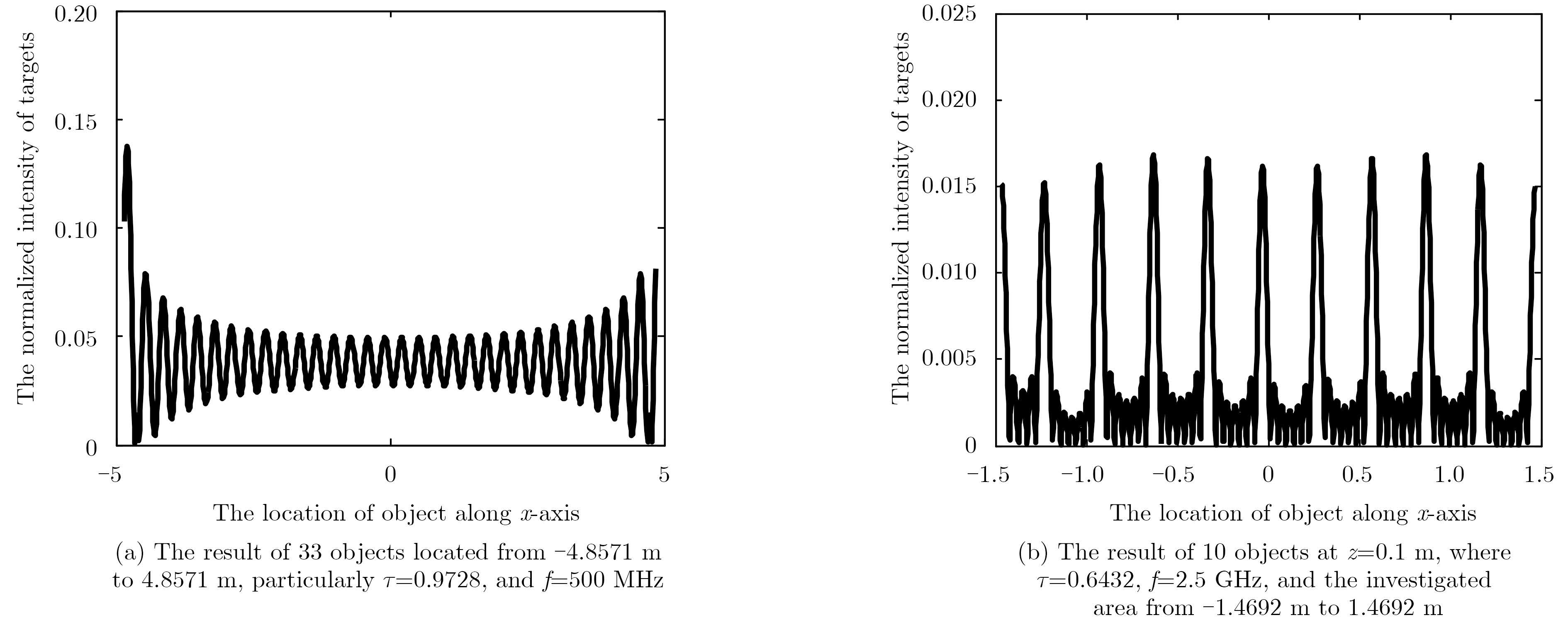
Secondly, we would like to investigate the effect of working frequency on imaging resolution, where simulation parameters are the same as those adopted above unless otherwise stated. For these two cases, the system parameters are set as follows: the number of transmitter and receiver are with same as above, but with inter-element space 0.3 m. Additionally, comparing Fig. 8(a) with Fig. 8(b), we can observe that the higher the operational frequency is, the better the achievable resolution is, and the smaller the detected area is.
|
Fig.8 simulation results when different work frequency f is set |
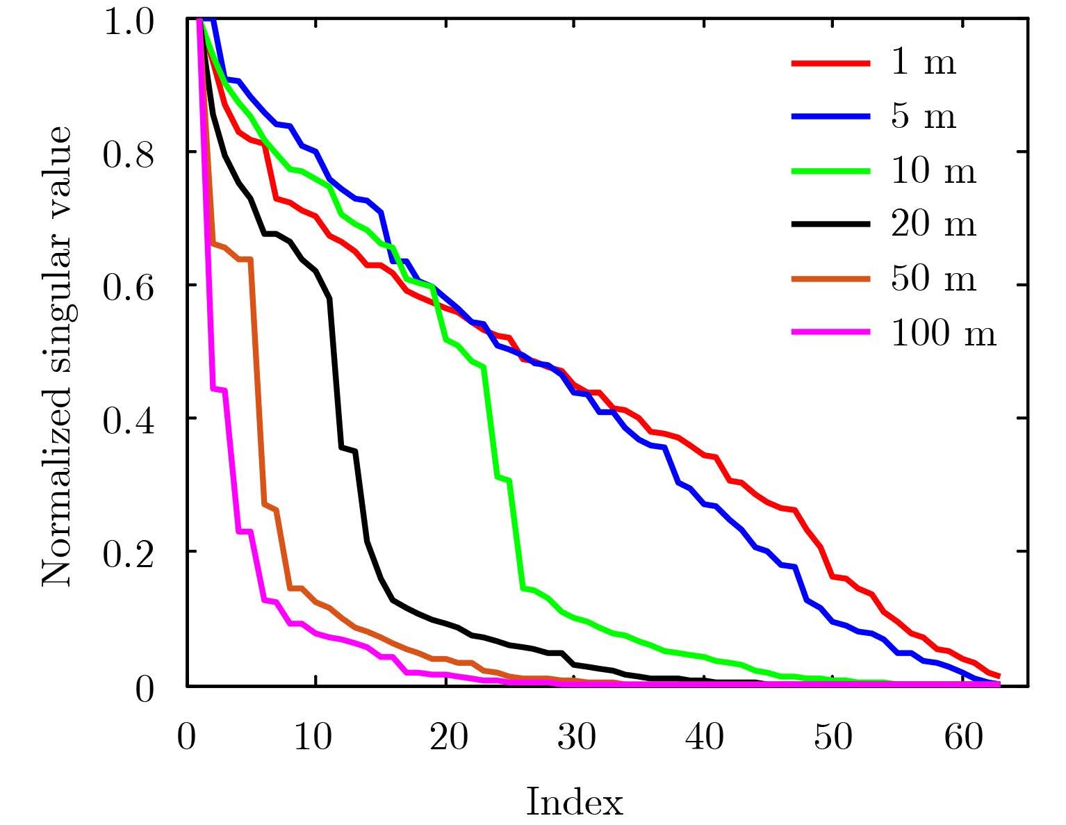
Finally, it is noted that there is a filter factor of $\frac{1}{{{k_z}k_z^\!\!{\rm{'}}}}$ in Eq. (14), which will weaken the imaging performance. Of course, the non-idea filter in practice will cause the degeneration of imaging resolution as well, as pointed out in Subsection 2.1. To look some insights into this point, we make following investigation. Eq. (4) can be formulated as a compact linear equation of y=Ax, where y means the MN measurements, x is the MN discrete values of the object spectrum $\tilde O$ with the resolution of $\frac{{4{ \tau } {k_0}}}{{MN}}$. The matrix A is of MN by MN, which is derived by Eq. (14). The well-texted Singular Value Decomposition (SVD) is used to asset the degree of independent measurements amongst MN measurements. Fig. 9 gives the behavior of singular value for different distances z between sensors and probed objects, where inter-element spacing 1 m are considered.
|
Fig.9 Demonstrates that the normalized SVD of A matrix when objects are set with different ranges z=1 m, 5 m, 10 m, 20 m, 50 m , and 100 m |
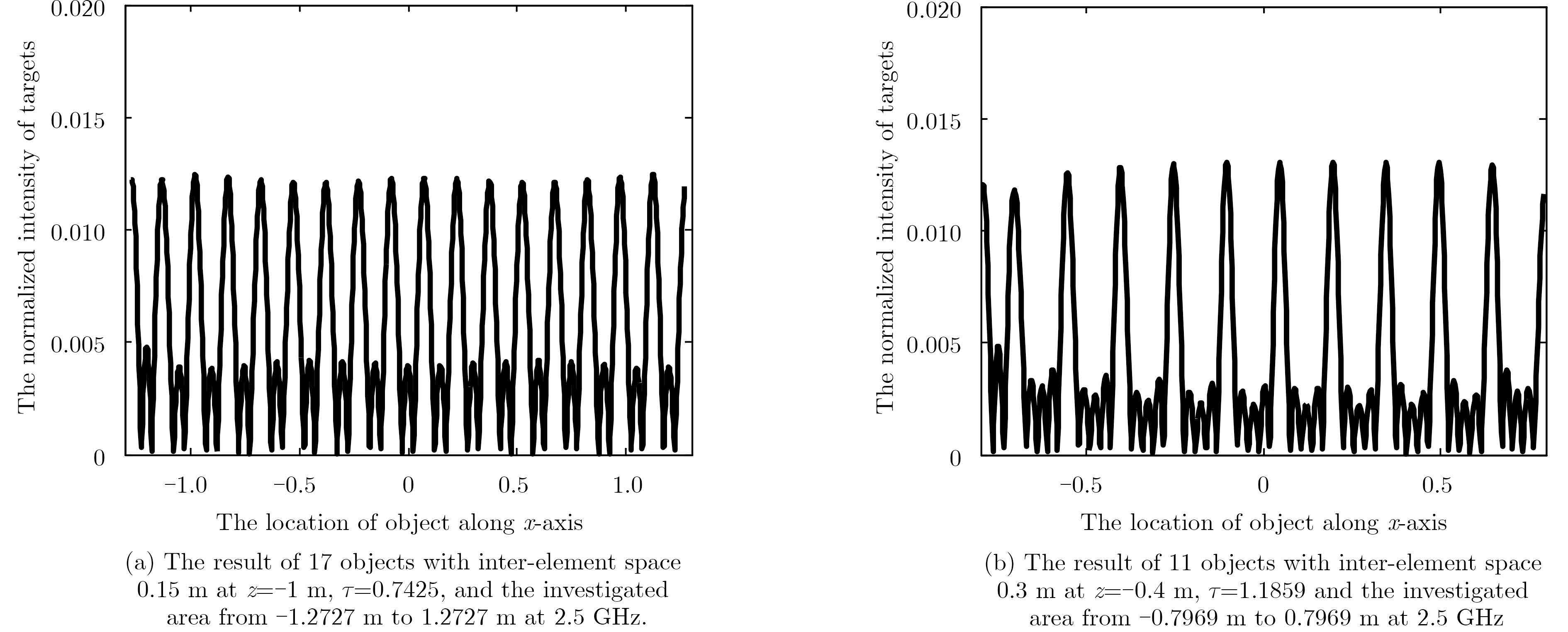
Some simulations have been done in flowing subsection for TWI scenario, which is regarded as an important application for our proposed method. Assuming the working frequency is 2.5 GHz. The number of transmitter and receiver are M=9 and N=7 respectively. The antennas are located at z=0.1 m. The permittivity and thickness of the wall are denoted as εr=9 and d=0.3 m. From simulation results of Fig. 10, the conclusion predicted in previous section can be verified.
|
Fig.10 The simulation results when different parameters are set for TWI scenario |
This paper extends the theory of coprime array for dealing with far-field DOA to that for dealing with the short-range radar detection by applying the spectrum expansion of Green's function. We theoretically and numerically demonstrate that the (M, N)-coprime array configuration is capable of retrieving the object spectrum over $\left[{ - 2{ \tau } {k_{0, }}2{ \tau } {k_0}} \right]$ with the resolution of $4{\rm{{ \tau } }}{k_0}/MN$, which is responsible for the spatial resolution of $\lambda /4\tau$. Moreover, numerical simulations are provided to show that the spatial spectrum co-prime array radar system can be applied to free-space imaging, TWI imaging identifying O(MN) targets just with O(M+N) sensors.
Appendix:This appendix is dedicated to demonstrate that if neglecting the term $\frac{1}{{{k_z}k_z^{\rm{'}}}}$ in Eq. (14), the (M, N)-coprime array is capable of recoving the complete spectrum of probed objects over the range of $\left[{ - 2{ \tau } {k_0}, 2{ \tau } {k_0}} \right]$ with the resolution of $\frac{{4{ \tau } {k_0}}}{{MN}}$, and that such measurements are non-redundant.
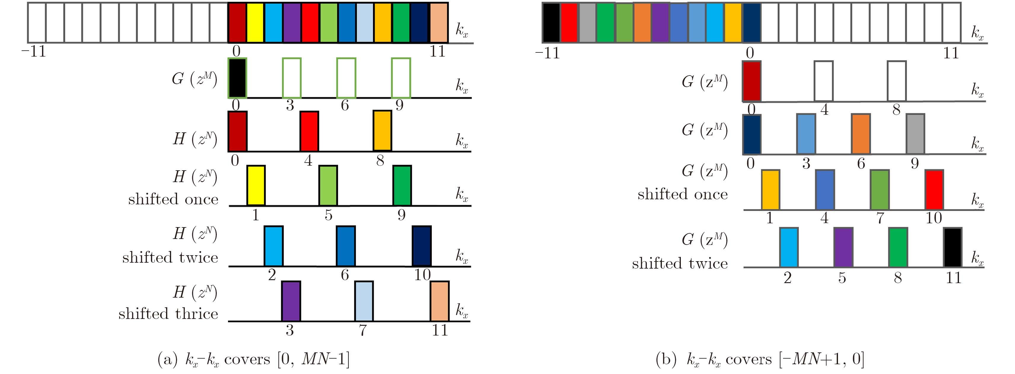
Firstly, we prove the completeness by showing that there is no holes in the achievable spectrum of object (see Fig. A-1). To that end, we would like to build more general notations involved in Subsection 2.2 as following:
|
Fig.A-1 When Nm+q=0 and Mn+p=0, kx-k'x can cover [0, MN–1] and [–MN+1, 0] shown in Fig. A1(a) and Fig. A1(b) respectively. So the (M, N)-coprime array can obtain all the information of spatial spectrum of objects in [-2τk0, 2τk0]. It is demonstrated for M=4 and N=3 |
| $\left\{ \begin{array}{l} \!\! {k_x} \!-\! p \!=\! M \cdot n \, , p \in \left[{0, M \!-\! 1} \right], n \in \left[{0, N \!-\! 1} \right]\\ \!\! k_x^{\rm{'}} \!-\! q \!=\!\! N \cdot m \, , q \in \left[{0, N \!-\! 1} \right]{\rm{, }}m \in \left[{0, M \!-\! 1} \right] \end{array} \right.$ | (A-1) |
From Eq. (1) one can deduce into
| ${k_x} - k_x^{\rm{'}} = M \cdot n - N \cdot m + p - q = M \cdot n + p$ | (A-2) |
In the second line, the assumption of N · m+q=0 has been used. Eq. (A-2) means that ${k_x} - k_x^{\rm{'}}$ can cover continuously the complete range of $0 \le {k_x} - k_x^{\rm{'}} \le MN - 1$ when p varies continuously from 0 to M–1. Similarly, If the assumption of M · n+p=0 is applied in Eq. (A-2), then one has ${k_x} - k_x^{\rm{'}} = - Nm - q$, which reveals that $ - MN + 1 \le {k_x} - k_x^{\rm{'}} \le 0$ can be achievable without any hole. To summarize, ${k_x} - k_x^{\rm{'}}$ must cover the complete range of [–MN+1, MN–1] without any hole. Thus, the series of MN measurements Rp, q ($0 \le p \le M - 1$ and $0 \le q \le N - 1$) are responsible for determining the complete spectrum of probed objects over $\left[{ - MN + 1, MN - 1} \right]$ of spatial spectrum of targets.
Secondly, we would like to demonstrate that the measurements of coprime array is of no redundancy in terms of the object spectrum over $\left[{ - MN + 1, MN - 1} \right]$. To this end, recall that the locations of object spectrum are described via Eq. (A-2). There is two cases.
Case 1 $p - q = p{\rm{'}} - q{\rm{'}} = \Delta $. This case corresponds to ${k_x} - k_x^{\rm{'}} = 0$, nonetheless, the measurements remains independent due to the factor of ${{\rm{e}}^{i{k_z}z - k_z^{\rm{'}}z}}$ in Eq. (14).
Case 2 $p - q \ne p{\rm{'}} - q{\rm{'}}$. For this case, ${k_x} - k_x^{\rm{'}}$ corresponds to different locations of object spectrum, which means the measurements apparently non-redundant.
| [1] |
Vaidyanathan P P and Pal P. Sparse sensing with co-prime samples and arrays[J].
IEEE Transactions on Signal Processing, 2011, 59 (2) : 573 –586.
( 0) 0)
|
| [2] |
Vaidyanathan P P and Pal P. Theory of sparse coprime sensing in multiple dimensions[J].
IEEE Transactions on Signal Processing, 2011, 59 (8) : 3592 –3608.
( 0) 0)
|
| [3] |
Qin S, Zhang Y D, and Amin M G. Generalized coprime array configurations for direction-of-arrival estimation[J].
IEEE Transactions on Signal Processing, 2015, 63 (6) : 1377 –1390.
( 0) 0)
|
| [4] |
Tan Z, Eldar Y C, and Nehorai A. Direction of arrival estimation using co-prime arrays: a super resolution viewpoint[J].
IEEE Transactions on Signal Processing, 2014, 62 (21) : 5565 –5576.
( 0) 0)
|
| [5] |
Tan Z and Nehorai A. Sparse direction of arrival estimation using co-prime arrays with off-grid targets[J].
IEEE Signal Processing Letters, 2014, 21 (1) : 26 –29.
( 0) 0)
|
| [6] |
Wang L and Li L. Through-the-wall target localization and tracking using co-prime array[C]. The 5th Asia-Pacific Conference on Synthetic Aperture Radar, Singapore, 2015.
( 0) 0)
|
| [7] |
Chew W C.
Waves and Fields in Inhomogeneous Media. Wiley-IEEE Press[M]. 1995 : 20 -23.
( 0) 0)
|
| [8] |
Li L, Zhang W, and Li F. A novel autofocusing approach for real-time through-wall imaging under unknown wall characteristics[J].
IEEE Transactions on Geoscience and Remote Sensing, 2010, 48 (1) : 423 –431.
( 0) 0)
|


