② 中国科学院电磁辐射与探测技术重点实验室 北京 100190;
③ 中国科学院大学 北京 100049;
④ 中国科学院 北京 100864
② Key Laboratory of Electromagnetic Radiation and Sensing Technology, Chinese Academy of Sciences, Beijing 100190, China;
③ University of Chinese Academy of Sciences, Beijing 100049, China;
④ Chinese Academy of Sciences, Beijing 100864, China
Microwave imaging technique for evaluation of hidden objects in a structure has been widely applied in the areas of breast tumor imaging,Ground Penetrating Radar (GPR),through-wall imaging and concealed weapon detection[1, 2, 3]. It has advantages over other Non-Destructive Evaluation (NDE) methods regarding low cost,portability, good penetration in nonmetallic materials, good resolution,and contactless detection. The imaging algorithms for microwave imaging technique can be classified into quantitative and qualitative methods[1, 4]. Quantitative methods retrieve the shapes and the electromagnetic parameters of unknown targets by solving a nonlinear inverse scattering problem. The disadvantage of quantitative methods is time consuming.
Qualitative methods usually make some assumptions and mathematical approximations for lower computational complexity[5]. The classical method is Frequency-Wavenumber (F-K) migration, also known as Stolt migration[3, 6]. F-K migration can be computed efficiently by Fast Fourier Transform (FFT). The algorithm works well for homogeneous background medium. However,in the case of layered medium,the image becomes unfocused and the hidden objects are incorrectly located. Another classical qualitative method involving Back-Projection (BP) algorithm is based on delay-and-sum beamforming. The image is reconstructed by summation of the backscattered data with proper phase compensation. The phase of the scattered signal in lossless medium is proportional to the round-trip distance in homogenous medium. For layered medium,the electromagnetic wave refracts across the discontinuity at the interface. The phase for two-layered medium can be solved numerically[7, 8]. But for three or more layers,the computational complexity will increase drastically. An efficient tomographic algorithm was proposed for 2-D microwave imaging through layered media in Ref. [9]. In this paper, an algorithm based on Phase Shift Migration (PSM) is presented for microwave imaging of layered medium.
PSM can handle velocity variations with depth[10]. F-K migration can be regarded as a special case of PSM. PSM originates from seismic engineering and geophysics[10, 11]. It recursively extrapolates the phase shift along depth in steps and uses the result of each step as input to the next iteration.
In this paper,the phase shift for layered medium is derived without recursion using the phase matching at the interface. So the image can be reconstructed in a fairly straight forward way. We also compensate the discontinuity of the interface using Fresnel transmission coefficients. The analysis on backscattered transfer function for layered medium makes clear to understand the assumptions and mathematical approximations in PSM.
This paper is organized as follows. Section 2 gives the derivation of PSM for layered medium. Section 3 analyzes the backscattered transfer function for layered medium and achieves the identical imaging equation by making some assumptions and approximations. In Section 4,numerical and experimental results are provided to show the effectiveness of PSM for layered medium. Finally,Section 5 gives a brief conclusion. 2 PSM for Layered Medium
PSM method was first proposed by Gazdag in 1978[10]. It is based on the concept of exploding source model[11],which assumes that a fictitious point source explodes at a reference time of $t=0$ at the target locationand radiates EM wave to the receiver. The velocity in the medium is replaced by half of the true propagation velocity for exploding source model.
Assuming that a point object is located at $r(x,y,z)$ and an antenna is located at $r'(x',y',z')$. The antenna illuminates the target with angular frequency . The antenna synthesizes a rectangular aperture on a plane $z=z'$ parallel to xy. If we make $z'=0$,EM field $f (x,y,z,t)$ can be described by the following 3-D scalar wave equation for homogeneous medium:
| $\left( {{{{\partial ^2}} \over {\partial {x^2}}} + {{{\partial ^2}} \over {\partial {y^2}}} + {{{\partial ^2}} \over {\partial {z^2}}} - {1 \over {v_m^{^2}}}{{{\partial ^2}} \over {\partial {t^2}}}} \right)f\left( {x,y,z,t} \right) = 0$ | (1) |
Applying 3-D Fourier transform to Eq. (1) over $x,y$,and $z$,we get
| $\left( {k_x^2 + k_y^2 + {{{\partial ^2}} \over {\partial {z^2}}} - {k^2}} \right)F\left( {{k_x},{k_y},z,w} \right){\rm{ = }}0$ | (2) |
| $F\left( {{k_x},{k_y},z,w} \right){\rm{ = }}F\left( {{k_x},{k_y},z{\rm{ = }}0,w} \right){{\rm{e}}^{jk{z^z}}}$ | (3) |
Doing 3-D inverse Fourier transform to $F({k_x},{k_y},z,w)$ over $x,y$,and $t$,we get:
| $\eqalign{ & f\left( {x,y,z,t} \right) = \int\!\!\!\int\!\!\!\int F \left( {{k_x},{k_y},z{\rm{ = }}0,w} \right) \cr & \qquad \qquad \qquad \cdot {{\rm{e}}^{jk{z^z}}}{{\rm{e}}^{jk{x^x}}}{{\rm{e}}^{jk{y^y}}}{{\rm{e}}^{j{w^t}}}d|{k_x}d{k_y}dw \cr} $ | (4) |
According to the imaging principle[11],the wavefront shape at $t=0$ corresponds to the reflector shape. Let $t=0$,we have the reflectivity at $r(x,y,z)$:
| $\eqalign{ & I\left( {x,y,z} \right) = f\left( {x,y,z,t = 0} \right) \cr & \, \qquad \qquad = \int {FT_{xy}^{ - 1}\left\{ {F\left( {{k_x},{k_y},z{\rm{ = }}0,w} \right){{\rm{e}}^{jk{z^z}}}} \right\}} dw \cr} $ | (5) |
The multiplication by ${{\rm{e}}^{jk{z^z}}}$ in Eq. (5) represents phase shift factor. It means that the extrapolation along $z$ direction in the frequencywavenumber domain is a phase shift operation.
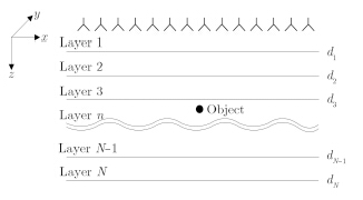
Consider a point object embedded in an Nlayer medium,as shown in Fig. 1. The electromagnetic properties vary with depth only,$i.e$. the z-direction. For layered medium,the $z$ component of the wavenumber vector is not constant:
| ${k_{iz}} = \sqrt {4{{\left( {w/{v_i}} \right)}^2} - k_x^2 - k_y^2} ,i = 1,2, \cdot \cdot \cdot ,N$ | (6) |

|
Fig.1 A point object embedded in a layered medium |
We can generally define the phase shift factor f or the point target in layer $n$ as:
| ${P_{\left( z \right)}} = {{\rm{e}}^{j{k_1}{z^{d1}}}}\left( {\prod\limits_{i = 1}^{n - 1} {{{\rm{e}}^{j{k_1}z\left( {{d_i} - {d_{i - 1} \ \ }} \right)}}} } \right){{\rm{e}}^{j{k_n}{z^{\left( {z - {d_{n - 1} \ \ }} \right)}}}}$ | (7) |
| $I\left( {x,y,z} \right) = \int {FT_{xy}^{ - 1}\left[ {F\left( {{k_x},{k_y},z{\rm{ = }}0,w} \right){{\rm{e}}^{j{k_1}{z^{d1}}}} \\ \qquad \qquad \quad \cdot \left( {\prod\limits_{i = 1}^{n - 1} {{{\rm{e}}^{j{k_i}z\left( {{d_i} - {d_{i - 1} \ \ }} \right)}}} } \right){{\rm{e}}^{j{k_n}{z^{\left( {z - {d_{n - 1 \ \ } }} \right)}}}}} \ \ \right]} dw$ | (8) |
| $I\left( {x,y,z} \right) = \int {FT} _{xy}^{ - 1}\left[ {F\left( {{k_x},{k_y},z = 0,w} \right) \\ \qquad \qquad \quad \cdot {{{e^{j{k_{1z}}^{_{^{d1}}}}}\left( {\prod\limits_{i = 1}^{n - 1} \ {{e^{j{k_{_{_{iz\left( {{d_{_i}} - {d_{_i}} - 1} \ \ \right)}}}}}}} } \ \ \ \ \right) \ {{\rm{e}}^{j{k_{nz\left( {z - {d_n} - 1} \right) \ \ }}}}} \over {\prod\limits_{i = 1}^{n - 1} {{T_{i,i + 1}} \ \ {T_{i + 1,i}}} }}} \ \ \right]dw$ | (9) |
Generally,when the antenna plane is $z=z'$, the reflectivity at $r(x,y,z)$ can be expressed as:
| $I\left( {x,y,z} \right) = \int {FT} _{xy}^{ - 1}\left[ {F\left( {{k_x},{k_y},z = z',w} \right) \\ \qquad \qquad \quad \cdot {{{e^{j{k_{1z}}^{\left( {_{^{d1}} - z'} \right)}}}\left( {\prod\limits_{i = 1}^{n - 1} {{e^{j{k_{^{_{_{_{iz\left( {{d_{_i}} - {d_{_i}} - 1} \ \ \right)}}}}}}}}} } \ \ \ \ \right){{\rm{e}}^{j{k_{nz\left( {z - {d_n} - 1} \ \ \right)}}}}} \over {\prod\limits_{i = 1}^{n - 1} {{T_{i,i + 1}} \ \ {T_{i + 1,i}}} }}} \ \ \right]dw$ | (10) |
The backscattered transfer function should be figured out to calculate the scattering field. Scattering problem can be typically formulated as the superposition of the scattering from a set of points,assuming that no interaction occurs between points. This leads to the following model:
| $f\left( {r',w} \right) = \mathop{\int\!\!\!\int\!\!\!\int}\limits_{\kern-5.5pt V} I \left( r \right){G_{GT}}\left( {r,r',w} \right)dr$ | (11) |
| $G_{RT}(r,r',w) = G_1(r,r',w)G_2(r,r',w)$ | (12) |
| $I\left( r \right) = \int {dw\int\!\!\!\int\limits_{S'} f } \left( {r',w} \right)G_{_{GT}}^{ - 1}\left( {r,r',w} \right)dr'$ | (13) |
| $\eqalign{ & {G_1}\left( {r,r',w} \right) = {{ - j} \over {8{\pi ^2}}}\int\!\!\!\int {{{{e^{ - j{k_x}\left( {x - x'} \right) - j{k_y}\left( {y - y'} \right)}}} \over {{k_{1z}}}}} \cr & \qquad \qquad \qquad \cdot {F_ - }\left( {z,z'} \right)d{k_x}d{k_y} \cr} $ | (14) |
| $\eqalign{ & {G_2}\left( {r',r,w} \right) = {{ - j} \over {8{\pi ^2}}}\int\!\!\!\int {{{{e^{ - j{k_x}\left( {x - x'} \right) - j{k_y}\left( {y - y'} \right)}}} \over {{k_{1z}}}}} \cr & \qquad \qquad \qquad \cdot {F_ + }\left( {z,z'} \right)d{k_x}d{k_y} \cr} $ | (15) |
Neglecting the upgoing wave below region n, ${F_ - }(z,z')$ and ${F_ + }(z',z)$ can be simplified as:
| ${F_ - }\left( {z,z'} \right) = {{\tilde T}_{1n}}{e^{^{ - j{k_{1z\left( {{d_1} - z'} \right)}}}}}{e^{^{ - j{k_{nz\left( {z - {d_n} - 1} \right)}}}}}$ | (16) |
| ${F_ + }\left( {z,z'} \right) = {{\tilde T}_{n1}}{e^{^{ - j{k_{1z\left( {{d_1} - z'} \right)}}}}}{e^{^{ - j{k_{nz\left( {z - {d_n} - 1} \right)}}}}}$ | (17) |
| ${\tilde T_{1n}} = \frac{{\prod\limits_{i = 1}^{n - 1} {{e^{ - j{k_{iz}}\left( {{d_i} - {d_{i - 1}}} \right)}}} {T_{i,i + 1}}}}{{1 - {R_{i + 1,i}}{{\tilde R}_{i + 1,i + 2}}{e^{ - j2{k_{i + 1,z}}\left( {{d_{i + 1}} - {d_i}} \right)}}}}$ | (18) |
| ${\tilde T_{n1}} = \frac{{\prod\limits_{i = 1}^{n - 1} {{e^{ - j{k_{iz}}\left( {{d_i} - {d_{i - 1}}} \right)}}{T_{i + 1,i}}} }}{{1 - {R_{i,i + 1}}{{\tilde R}_{i,i - 1}}{e^{ - j2{k_{iz}}\left( {{d_i} - {d_{i - 1}}} \right)}}}}$ | (19) |
| $\eqalign{ & {G_{RT}}(r,r',w) \cr & \qquad = \left( {\prod\limits_{i = 1}^{n - 1} {{T_{i,i + 1}}{T_{i + 1,i}}} } \right) \cr & \qquad \quad \cdot {\left( {\int\!\!\!\int {{e^{ - j{k_x}\left( {x - x'} \right) - j{k_y}\left( {y - y'} \right)}}\left( {\prod\limits_{i = 1}^{n - 1} {{e^{ - j{k_{iz}}\left( {{d_i} - {d_i} - 1} \right)}}} } \right) \!\!\!\!\!\!\!\!\!\!\!\!\!\!\!\!\!\!\!\! \\ \cdot } {e^{^{ - j{k_{1z\left( {{d_1} - z'} \right)}}}}}{e^{^{ - j{k_{nz\left( {z - {d_n} - 1} \right)}}}}}d{k_x}d{k_y}} \right)^2} \cr} $ | (20) |
| $\eqalign{ & {G_{RT}}(r,r',w) \cr & \qquad = \left( {\prod\limits_{i = 1}^{n - 1} {{T_{i,i + 1}}{T_{i + 1,i}}} } \right) \cr & \qquad \quad \cdot \int\!\!\!\int {{e^{ - j{k_x}\left( {x - x'} \right) - j{k_y}\left( {y - y'} \right)}}\left( {\prod\limits_{i = 1}^{n - 1} {{e^{ - j{k_{iz}}\left( {{d_i} - {d_i} - 1} \right)}}} } \right)} \cr & \qquad \quad \cdot {e^{^{ - j{k_{1z\left( {{d_1} - z'} \right)}}}}}{e^{^{ - j{k_{nz\left( {z - {d_n} - 1} \right)}}}}}d{k_x}d{k_y} \cr} $ | (21) |
| $I\left( {x,y,z} \right) = \int {FT} _{xy}^{ - 1}\left[ {F{T_{xy}}\left[ {f\left( {x',y',z',w} \right)} \right] \\ \qquad \qquad \quad \cdot {{{e^{j{k_{1z}}^{\left( {_{^{d1}} - z'} \right)}}}\left( {\prod\limits_{i = 1}^{n - 1} {{e^{j{k_{^{_{_{_{iz\left( {{d_{_i}} - {d_{_i}} - 1} \ \right)}}}}}}}}} } \ \ \ \right){{\rm{e}}^{j{k_{nz\left( {z - {d_n} - 1} \right)}}}}} \over {\prod\limits_{i = 1}^{n - 1} {{T_{i,i + 1}} \ \ \ {T_{i + 1,i}}} }}} \ \ \ \right]dw$ | (22) |
The PSM for layered medium can be viewed as an approximate inversion of the inverse scattering problem. The assumption of the proposed algorithm can be summarized as follows. (1) Under first-order Born approximation,multiple scattering within the target is ignored. (2) For the object buried in layer n,the upgoing wave below region $n$ is ignored. That means the generalized reflection coefficient for the layered medium below region $n$ is set to zero. (3) The multiple reflections in layered medium are not considered. (4) The propagation decay is ignored. (5) The imaging area is in the far field of the antenna. 4 Results
In order to show the high computational efficiency and accurate image formation of the algorithm, both numerical simulation and experimental measurement are demonstrated in this section. Matlab is used to perform the simulation and imaging on a 64 bit PC with 16 GB RAM and four-core 2.5 GHz CPU. 4.1 Numerical results
Firstly,we present a numerical example for the imaging of the targets buried in a layered medium shown in Fig. 2. The antenna is placed on the plane $z=0$ with a standoff distance of 2 cm. The area is scanned along x direction from $x=-15$ cm to 15 cm with a step size of 0.5 cm. The first layer is wood with dielectric constant $ε_1=2$. The second layered is concrete with dielectric constant $ε_2=6$. Thicknesses of wood and concrete are chosen to be 5 cm and 7.5 cm,respectively. The buried objects are metallic cylinders with 1.5 cm radius located at (-5 cm,5 cm) and (5 cm,11 cm). The measured data is generated in time domain using 2-D Finite Difference Time Domain (FDTD) method and is transformed to frequency domain by Fourier transform. The frequency range covers from 3 GHz to 8 GHz with a step size of 25 MHz.

|
Fig.2 Simulation model |
The reflected signal from interfaces of layers is relatively stronger compared with the scattered signal from targets. To clearly show the image of targets,we can estimate the background by averaging collected data over the scanning area and subtract the average from the collected data.
| $f'\left( {x,w} \right) = f\left( {x,w} \right) - \sum\limits_x {{{f\left( {x,w} \right)} \over {{N_x}}}} $ | (23) |
The collected data was processed by the proposed algorithm and $F-K$ migration for comparison. For $F-K$ migration,the effective dielectric constant can be approximately obtained by Root Mean Square (RMS)[16]:
| $\varepsilon_{RMS} = {\left( {{{\sum\limits_{i = 1}^N {\varepsilon _i^2\Delta {t_i}} } \over {\sum\limits_{i = 1}^N {\Delta {t_i}} }}} \right)^{{1 \over 2}}}$ | (24) |
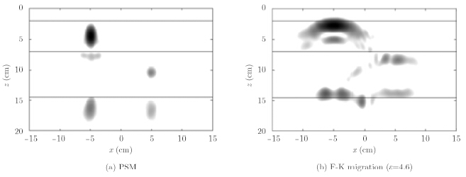
Fig. 3(a) shows the reconstructed image using the proposed algorithm. The pixel size of the image is 256×256. It takes only 1 s to get the image. However,more than 2 min is needed to reconstruct the image processed by $BP$ algorithm. The horizontal lines are added to show the interfaces of layers. The targets are correctly located. In Fig. 3(a),the shadows at the interfaces of layered medium are introduced by the interaction between the objects and the layered medium. The image processed by F-K migration with RMS dielectric constant is shown in Fig. 3(b). As can be seen from Fig. 3(b),the targets are displaced away from the target locations. The image entropy is employed to quantitatively evaluate the focus quality of reconstructed images. The better focus corresponds to smaller entropy. The entropy is defined as[17]:
| $\xi = {{{{\left( {\sum {\sum {{{\left| {{x_{ij}}} \right|}^2}} } } \right)}^2}} \over {\sum {\sum {{{\left| {{x_{ij}}} \right|}^4}} } }}$ | (25) |

|
Fig.3 Results for simulation |
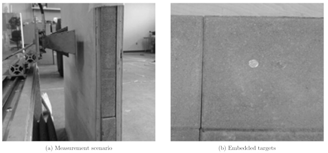
The proposed imaging algorithm has been validated by experimentally for detecting an object embedded in a three-layered medium. The experimental setup consists of Agilent N5230A (10 MHz~20 GHz)VNA and AEL H-1498 doubleridge horn antenna mounted on a 1-D scanner. The scanner moves the antenna parallel to the layered medium with a standoff distance of 3 cm. A 30.48 cm aperture is synthesized with 25 measurements spaced 1.27 cm in $x$ direction. The aperture center is set to $x=0$,$z=0$,where $z=0$ corresponds to the measurement plane. Data is collected at 1001 points in the frequency range from 2 GHz to 12 GHz with a step of 10 MHz. The complex S-parameter S11 is used as the radar response for layered medium imaging. The scenario is shown in Fig. 4(a). The three layered medium is comprised by two wood blocks and concrete block. The thicknesses of wood block and concrete block are 1.85 cm and 4.46 cm,respectively. Two metallic disks with 1.3 cm radius are placed at the interface between the second layer and third layer,as shown in Fig. 4(b). The locations of the embedded object are (-2 cm,9.3 cm) and (3 cm,9.3 cm).

|
Fig.4 Measurement scenario and embedded targets |
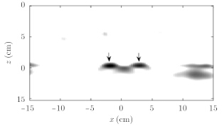
The dielectric constants of wood block and concrete block are estimated as 2.12 and 7.25 by time domain reflectometry[17]. Fig. 5 shows the resulting image of embedded targets processed by 6 Journal of Radars Vol. x the proposed algorithm. The pixel size of the image is 256×256. The processing time is about 2.5 second. The indications of metallic disks in the image are focused and properly located. The interaction of the two objects leads to the ghost located at the center of the object locations. Faint artifacts at the left and right sides exist because the concrete block is not homogeneous.

|
Fig.5 Reconstructed imaging of embedded targets |
In this paper,phase shift migration for imaging of layered medium is proposed. Based on the analysis of backscattered transfer function,phase shift migration for layered medium can be viewed as an approximation of inverse problem. The proposed algorithm for layered medium is efficient due to the following reasons. Firstly,the coherent summation in BP algorithm is computed efficiently with FFT. Secondly,the solving of nonlinear equation in order to find the refraction points in BP algorithm is avoided. Only the phase shift factor is updated along with depth. Thirdly,instead of the pixel-by-pixel reconstruction in BP algorithm,the proposed algorithm efficiently reconstructs the image with IFFT. Numerical and experimental results are presented to show the effectiveness of the proposed algorithm for real-time imaging of layered medium.
Acknowledgement The authors would like to thank ElectroScience Laboratory,the Ohio State University for providing the experimental data.| [1] | Pastorino M. Microwave Imaging[M]. Hoboken, NJ, US:John Wiley & Sons, Inc., 2010: 1–4.( 2) 2) |
| [2] | Daniels DJ. EM Detection of Concealed Targets[M].Hoboken, New Jersey, US: John Wiley & Sons, Inc.,2010: 1–19.( 1) 1) |
| [3] | Sheen DM, McMakin DL, and Hall TE. Three-dimensional millimeter-wave imaging for concealed weapon detection[J]. IEEE Transactions on Microwave Theory and Techniques, 2001, 49(9): 1581–1592.( 3) 3) |
| [4] | Li L, Zhang W, and Li F. Derivation and discussion of the SAR migration algorithm within inverse scattering problem: theoretical analysis[J]. IEEE Transactions on Geoscience and Remote Sensing, 2010, 48(1): 415–422.( 1) 1) |
| [5] | Gilmore C, Jeffrey I, and LoVetri J. Derivation and comparison of SAR and frequency-wavenumber migration within a common inverse scalar wave problem formulation[J]. IEEE Transactions on Geoscience and Remote Sensing, 2006, 44(6): 1454–1460.( 1) 1) |
| [6] | Stolt RH. Migration by Fourier transform[J]. Geophysics, 1978, 43(1): 23–48.( 1) 1) |
| [7] | Ahmad F, Amin MG, and Kassam SA. Synthetic aperture beamformer for imaging through a dielectric wall[J]. IEEE Transactions on Aerospace and Electronic Systems, 2005, 41(1): 271–283.( 1) 1) |
| [8] | Jeong P, Han S, and Kim K. Efficient time-domain back projection algorithm for penetrating imaging radar[J]. Microwave and Optical Technology Letters, 2011, 53(10): 2406–2411.( 1) 1) |
| [9] | Zhang W. Two-dimensional microwave tomographic algorithm for radar imaging through multilayered media[J]. Progress in Electromagnetics Research, 2014, 144: 261–270.( 1) 1) |
| [10] | Gazdag J. Wave equation migration with phase-shift method[ J]. Geophysics, 1978, 43(7): 1342–1351.( 2) 2) |
| [11] | Yilmaz O. Seismic Data Processing[M]. Tulsa, OK, US: Society of Exploration Geophysicists, 1987: 250–267.( 3) 3) |
| [12] | Chow WC. Waves and Fields in Inhomogeneous Media[M]. New York, NY, US: the Institute of Electrical and Electronics Engineers, Inc., 1995: 45–79.( 3) 3) |
| [13] | Chew WC and Chen S. Response of a point source embedded in a layered medium[J]. IEEE Antennas and Wireless Propagation Letters, 2003, 2(1): 254–258.( 1) 1) |
| [14] | Zhang W and HoorfarA. Three-dimensional real-time through-the-wall radar imaging with diffraction tomographic algorithm[J]. IEEE Transactions on Geoscience and Remote Sensing, 2013, 51(7), 4155–4163.( 1) 1) |
| [15] | Zhang W and Hoorfar A. Two-dimensional diffraction tomographic algorithm for through-the-wall radar imaging[J]. Progress in Electromagnetics Research B, 2011, 31: 205–218.( 1) 1) |
| [16] | Taner MT and Koehler F. Velocity spectra-digital computer derivation and applications of velocity functions[J]. Geophysics, 1969, 34(6): 859–881.( 1) 1) |
| [17] | Kosmas P and Rappaport C. Time reversal with the FDTD method for microwave breast cancer detection[J]. IEEE Transactions on Microwave Theory and Techniques, 2005, 53(7): 2317–2323.( 2) 2) |
| [18] | Aftanas IM. Through-wall imaging with UWB radar system[D]. [Ph.D. dissertation], Technical Universityof Kosice,2009: 56–66.( 0) 0) |
 2015, Vol. 4 Issue (4): 431–438
