②University of Chinese Academy of Sciences, Beijing 100049, China
③China Academy of Launch Vehicle Technology, Beijing 100076, China
②中国科学院大学 北京 100049
③中国运载火箭技术研究院 北京 100076
Synthetic Aperture Radar (SAR) is an advanced imaging sensor,which provides high-reso-lution images of static scenes. With the increasing demands of both civilian and military industry,Ground Moving Target Imaging (GMTIm) is also becoming an important application to enhance the surveillance capability of modern SAR systems.
Moving targets are defocused and dislocated in SAR images due to their unknown motions. In most existing GMTIm algorithms,the radar platform velocity is assumed to be constant during the data acquisition,and the motion of the moving target is modeled by constant velocity and constant acceleration. In this condition,an algorithm to analyze the optimal and suboptimal schemes for detection and image of ground moving target is presented by Ref. [1]. Ref. [2] also an presented approach to focus moving targets by two-dimensional parameter searching. Ref. [3] has an advanced algorithm to focus the moving target through time-frequency analysis technique in range-Doppler domain. A new approach,to accomplish the azimuth compression of the moving target in range-frequency domain,is presented by Ref. [4]. However,these models above are still unsuitable for the real data processing due to the non-ideal motion errors. Therefore,the applications of these algorithms showed limitations in the real data processing.
In real situation,the non-ideal motion errors come from two sources: the platform and the moving target itself. Ref. [5] has proposed to utilize the Phase Gradient Autofocus (PGA) technique to compensate the residual phase error of the moving target regardless of the forms of the motion errors. However,the PGA technique was just employed to compensate the high-order phase error of the moving target,and it is insufficient in the real data processing since the Doppler centroid of the moving target is also affected by the motion errors.
In this paper,a practical model of the moving target is established concerning on the existence of non-ideal motion errors. Based on this model,the impacts of the platform velocity and the cross-track velocity error on the Doppler centroid of the moving target are analyzed,and a non-ideal motion error compensation algorithm based on the Inertial Navigation System (INS) data and the range walk trajectory is proposed. The energy of the moving target will spread on multiple Doppler centroids if these non-ideal motion errors are not accurately compensated,and they can not be corrected by the PGA technique. Simulated data is utilized to prove the rationality of the non-ideal motion error analysis and the effectiveness of the non-ideal motion error compensation algorithm.
This paper is organized as follows. In Section 2,the echo model of moving targets is described. In Section 3,we analyze the two non-ideal motion errors,which affect the Doppler centroid of the moving target in detail. In Section 4,the proposed non-ideal motion error compensation algorithm is introduced. In Section 5,the simulated data is utilized to illustrate the effectiveness of the proposed algorithm. Finally,some conclusions are given in Section 6.
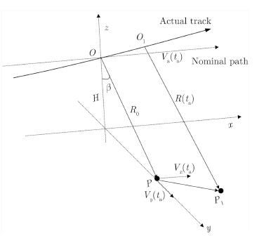
2 Signal ModelThe imaging geometry relationship between the platform and the moving target for broadside SAR is shown in Fig. 1,where the solid line indicates the actual flight path,and the dashed line is a virtual trajectory,conventionally nominated as “the ideal trajectory” or “the nominal path”. In ideal case,the Antenna Phase Center (APC) of the radar moves along the nominal path at a constant velocity[6, 7, 8, 9].
|
Fig.1 Broadside geometry of the moving target |
During the azimuth time interval Ta,the platform flies along the actual flight path from O to O1,while the moving target moves from P to P1. In order to analyze the echo of the moving target with non-ideal motion errors,the velocities of the platform and the moving target vary with the discrete azimuth time ta in our model. Va(ta) denotes the ideal platform velocity; Vx(ta) and Vy(ta) denote the along- and cross-track velocities of the moving target,respectively. R0 and R(ta) represent the nearest and instantaneous slant ranges between the platform and the moving target,respectively.
The actual and nominal APC position at ta is [X(ta),Y(ta),Z(ta)] and [Va(ta)ta,0,0],respec-tively. The motion error vector,defined as the displacement between the actual and nominal path,is [X(ta)-Va(ta)ta,Y(ta),Z(ta)],where Y(ta) and Z(ta) denote the motion displacement in the normal plane,i.e.,cross-track motion error. Absence of any squint is assumed and the illuminated surface is supposed flat.
Considering a moving point target P(x0,y0,z0) and P1(x0+Vx(ta)ta,y0+Vy(ta)ta,z0),the instantaneous slant range can be represented as
| $\begin{aligned} R\left( {{t_{\rm{a}}}} \right) = & \left( {{{\left( {X\left( {{t_{\rm{a}}}} \right) - {x_0} - {V_x}\left( {{t_{\rm{a}}}} \right){t_{\rm{a}}}} \right)}^2} + \left( {Y\left( {{t_{\rm{a}}}} \right) - {y_0}} \right.} \right.\\ & {\left. {{{\left. { - {V_y}\left( {{t_{\rm{a}}}} \right){t_{\rm{a}}}} \right)}^2} + {{\left( {Z\left( {{t_{\rm{a}}}} \right) - {z_0}} \right)}^2}} \right)^{1/2}}\\ = & \left( {{{\left( {X\left( {{t_{\rm{a}}}} \right) - {x_0}} \right)}^2} + {{\left( {Y\left( {{t_{\rm{a}}}} \right) - {y_0}} \right)}^2}} \right. + \left( {Z\left( {{t_{\rm{a}}}} \right)} \right.\\ & {\left. { - {z_0}} \right)^2} - 2\left[{\left( {X\left( {{t_{\rm{a}}}} \right) - {x_0}} \right){V_x}\left( {{t_{\rm{a}}}} \right) + \left( {Y\left( {{t_{\rm{a}}}} \right)} \right.} \right.\\ & {\left. {\left. {\left. { - {y_0}} \right){V_y}\left( {{t_{\rm{a}}}} \right)} \right]{t_{\rm{a}}} + \left[{{V_x}{{\left( {{t_{\rm{a}}}} \right)}^2} + {V_y}{{\left( {{t_{\rm{a}}}} \right)}^2}} \right]{t_{\rm{a}}}^2} \right)^{1/2}} \end{aligned}$ | (1) |
| $\begin{aligned} R({t_{\rm{a}}}) = & \left( {{{\left( {X\left( {{t_{\rm{a}}}} \right) - {x_0}} \right)}^2} + Y{{\left( {{t_{\rm{a}}}} \right)}^2} + Z{{\left( {{t_{\rm{a}}}} \right)}^2} + {R_0^2} - 2{R_0}\left[{Y\left( {{t_{\rm{a}}}} \right)\sin \beta + Z\left( {{t_{\rm{a}}}} \right)\cos \beta } \right]} \right.\\ & \! {\left. { \; - 2\left[{\left( {X\left( {{t_{\rm{a}}}} \right) \! - \! {x_0}} \right){V_x}\left( {{t_{\rm{a}}}} \right) \! + \! \left( {Y\left( {{t_{\rm{a}}}} \right) - {y_0}} \right){V_y}\left( {{t_{\rm{a}}}} \right)} \right]{t_{\rm{a}}} + \left[{{V_x}{{\left( {{t_{\rm{a}}}} \right)}^2} + {V_y}{{\left( {{t_{\rm{a}}}} \right)}^2}{t_{\rm{a}}^2}} \right]} \right)^{1{\rm{/}}2}}\\ \approx & \left( {{{\left( {X\left( {{t_{\rm{a}}}} \right) - {x_0}} \right)}^2} + {R_0^2} - 2{R_0}\left[{Y\left( {{t_{\rm{a}}}} \right)\sin \beta + Z\left( {{t_{\rm{a}}}} \right)\cos \beta } \right]} \right.\\ & \!\! {\left. { \ - 2\left[{\left( {X\left( {{t_{\rm{a}}}} \right) \! - \! {x_0}} \right){V_x}\left( {{t_{\rm{a}}}} \right) \! + \! \left( {Y\left( {{t_{\rm{a}}}} \right) \! - {y_0}} \right){V_y}\left( {{t_{\rm{a}}}} \right)} \right]{t_{\rm{a}}} + \left[{{V_x}{{\left( {{t_{\rm{a}}}} \right)}^2} + {V_y}{{\left( {{t_{\rm{a}}}} \right)}^2}} \right]{t_{\rm{a}}^2}} \right)^{1{\rm{/}}2}}\\ \approx & {R_0} + \frac{{{{\left( {X\left( {{t_{\rm{a}}}} \right) - {x_0}} \right)}^2}}}{{2{R_0}}} - \left[{Y\left( {{t_{\rm{a}}}} \right)\sin \beta + Z\left( {{t_{\rm{a}}}} \right)\cos \beta } \right]\\ & - \frac{{\left( {X\left( {{t_{\rm{a}}}} \right) - {x_0}} \right){V_x}\left( {{t_{\rm{a}}}} \right) + \left( {Y\left( {{t_{\rm{a}}}} \right) - {y_0}} \right){V_y}\left( {{t_{\rm{a}}}} \right)}}{{{R_0}}}{t_a} + \frac{{{V_x}{{\left( {{t_{\rm{a}}}} \right)}^2} + {V_y}{{\left( {{t_{\rm{a}}}} \right)}^2}}}{{2{R_0}}}{t_{\rm{a}}^2}\\ = & {R_0} + \frac{{{{\left( {X\left( {{t_{\rm{a}}}} \right) - {x_0}} \right)}^2}}}{{2{R_0}}} + \Delta R\left( {{t_{\rm{a}}}} \right) + \Delta V\left( {{t_{\rm{a}}}} \right) \end{aligned}$ | (2) |
The instantaneous slant range has been separated into four terms in Eq. (2). The first term is the closest distance. The second and third terms indicate the along-track and cross-track motion error caused by the radar platform velocity,while the last term shows the error induced by the moving target velocity.
where| $\left. {\begin{array}{*{20}{c}} {\Delta R\left( {{t_{\rm{a}}}} \right) = - Y\left( {{t_{\rm{a}}}} \right)\sin \beta - Z\left( {{t_{\rm{a}}}} \right)\cos \beta }\\ \begin{aligned} \hspace{-3pt} \Delta V\left( {{t_{\rm{a}}}} \right) = & - \left( {\frac{{\left( {X\left( {{t_{\rm{a}}}} \right) - {x_0}} \right){V_x}\left( {{t_{\rm{a}}}} \right)}}{{{R_0}}}} \right.\\ & + \left. {\frac{{\left( {Y\left( {{t_{\rm{a}}}} \right) - {y_0}} \right){V_y}\left( {{t_{\rm{a}}}} \right)}}{{{R_0}}}} \right){t_{\rm{a}}}\\ & + \frac{{{V_x}{{\left( {{t_{\rm{a}}}} \right)}^2} + {V_y}{{\left( {{t_{\rm{a}}}} \right)}^2}}}{{2{R_0}}}t_{\rm{a}}^2 \end{aligned} \end{array}} \right\}$ |
After the range compression,the echoes of the moving target can be expressed as
| ${{s}_{0}}\left( {{t}_{\text{a}}},{{t}_{\text{r}}} \right)={{A}_{0}}{{\omega }_{\text{a}}}\left( {{t}_{\text{a}}} \right)\sin \text{c}\left[ \pi {{B}_{\text{r}}}\left( {{t}_{\text{r}}}-\frac{2R\left( {{t}_{\text{a}}} \right)}{\text{c}} \right) \right] \\ \qquad \qquad \quad \cdot \exp \left( -\text{j}\frac{4\pi }{\lambda }R\left( {{t}_{\text{a}}} \right) \right)$ | (3) |
| ${{s}_{0}}\left( {{t}_{\text{a}}},{{t}_{\text{r}}} \right)={{A}_{0}}{{\omega }_{\text{a}}}\left( {{t}_{\text{a}}} \right)\text{sinc}\left[ \pi {{B}_{\text{r}}}\left( {{t}_{\text{r}}}-\frac{2{{R}_{0}}}{\text{c}} \right) \right]\exp \left( -\text{j}\frac{4\pi }{\lambda }{{R}_{0}} \right)\exp \left( -\text{j}\frac{4\pi }{\lambda }\frac{{{\left( X\left( {{t}_{\text{a}}} \right)-{{x}_{0}} \right)}^{2}}}{2{{R}_{0}}} \right)$ $ \qquad \qquad \cdot \exp \left( \text{j}\frac{4\pi }{\lambda }\frac{\left( X\left( {{t}_{\text{a}}} \right)-{{x}_{0}} \right){{V}_{x}}\left( {{t}_{\text{a}}} \right)+\left( Y\left( {{t}_{\text{a}}} \right)-{{\text{y}}_{0}} \right){{V}_{y}}\left( {{t}_{\text{a}}} \right)}{{{R}_{0}}}{{t}_{\text{a}}} \right)\exp \left( -\text{j}\frac{4\pi }{\lambda }\frac{{{V}_{x}}{{({{t}_{\text{a}}})}^{2}}+{{V}_{y}}{{({{t}_{\text{a}}})}^{2}}}{2{{R}_{0}}}t_{\text{a}}^{2} \right)$ $ \qquad \qquad \quad \cdot \exp \!\! \left(\! \text{j}\frac{4\pi {{K}_{\text{r}}}}{\text{c}}\frac{(X({{t}_{a}})- \! \! {{x}_{0}}){{V}_{x}}({{t}_{\text{a}}})+(Y({{t}_{\text{a}}})-{{\text{y}}_{0}}){{V}_{y}}({{t}_{\text{a}}})}{{{R}_{0}}}{{t}_{\text{r}}}{{t}_{\text{a}}} \right) \! \! \exp \left(\! \!\!-\text{j}\frac{4\pi {{K}_{\text{r}}}}{\text{c}}\frac{{{V}_{x}}{{({{t}_{\text{a}}})}^{2}}+{{V}_{y}}{{({{t}_{\text{a}}})}^{2}}}{2{{R}_{0}}}{{t}_{\text{r}}}t_{\text{a}}^{2} \right)$ | (4) |
In Eq. (4),the second,third,and fourth exponential terms represent the Doppler centroid and the high-order Doppler phase of the moving target,respectively. The fifth exponential term represents the range walk,and the sixth exponential term represents the range curve. In conventional GMTIm algorithms,in which Va(ta),Vx(ta),and Vy(ta) are assumed to be independent of ta,the Doppler centroid and the high-order Doppler phase of the moving target is the first- and second-order term of ta,respectively. Therefore,after the range cell migration corrected,the moving target can be focused by the estimation values of the first- and second-order Doppler parameters.
Since Va(ta),Vx(ta),and Vy(ta) all vary with ta in our model,however,the Doppler centroid might be inconstant,and higher order Doppler phase errors might appear in echo. The high-
order phase errors can be compensated by using the PGA technique. As to the Doppler centroid,nevertheless,the PGA technique is ineffective.
If the Doppler centroid of the moving target is not constant during Ta,the energy of the moving target will spread on multiple Doppler centroid,which severely deteriorates the imaging resolution even though the high-order phase errors are accurately compensated. It is noted from the second exponential term of Eq. (4) that the Doppler centroid of the moving target is determined by ta and Vx(ta). ta is sampled by the Pulse Repetition Frequency (PRF) of the SAR platform,whereas Vx(ta) denotes the actual cross-track motion of the moving target. Therefore,we will analyze the relationship between the motion errors of the platform,the moving target and the Doppler centroid in the next section.
3 Non-ideal Motion Error Analysis 3.1 Platform velocity errorCompensation for the non-ideal motion error of the platform is important in the real SAR data imaging. Due to the air turbulence and the restriction of the platform control system,the platform’s velocity can not maintain constant on a linear course during the data acquisition in most practical situations. The non-ideal motion error of the platform can be classified into two sorts[10]: the non-ideal course that is not a straight line along the azimuth direction and the inconstant platform velocity during the data acquisition. The non-ideal course of the platform can be corrected by the INS data. In the case that INS data is not accurate enough,data-based techniques,such as the PGA,can be adopted to further correct this sort of motion error[11].
In stationary SAR imaging,the platform velocity error will lead to the inconstant Doppler modulation rate. To solve this problem,the SAR system is changed from a time-constant sampling system to a spatial-constant sampling one[12]. The PRF of the spatial-constant sampling system is adjusted to the platform velocity,so as to keep the PRF-to-velocity ratio constant. In such systems,the time-variant PRF can be defined as
| ${\rm{PRF}}({t_{\rm{a}}}) = {K_v} \cdot {V_{\rm{a}}}\left( {{t_{\rm{a}}}} \right)$ | (5) |
In the spatial-constant sampling system,the Doppler bandwidth of the clutter can be expressed as
| ${B_{\rm{a}}}({t_{\rm{a}}}) = \frac{{2{V_{\rm{a}}}\left( {{t_{\rm{a}}}} \right)}}{{{L_{\rm{a}}}}}$ | (6) |
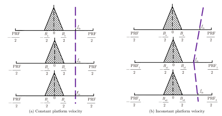
According to Eq. (5) and Eq. (6),both Ba(ta) and PRF(ta) are linear functions of Va(ta). Therefore,the energy of the clutter in each azimuth sample can be coherently accumulated during the data acquisition. The Doppler centroid of the moving target,which can be expressed as
| ${f_{{\rm{dc}}}} = \frac{{2{V_x}}}{\lambda}$ | (7) |
|
Fig.2 Impact of the platform velocity error on the Doppler centroid of moving target |
In Fig. 2,the purple breaking lines represent the Doppler histories of moving target. In Fig. 2(a), the Doppler history of the moving target is a rectilinear trajectory. On the contrary,the trajectory is not a straight line in Fig. 2(b) with the changes of PRF. In the case of Fig. 2(b),the energy of the moving target can not be compressed into one Doppler centroid. In practical airborne SAR applications,especially for unmanned missions,the platform velocity changes severely in the presence of the air turbulence. Therefore,the platform velocity error must be compensated for moving target focusing[13, 14].
3.2 Cross-track velocity error of moving targetIn most practical situations,the cross-track velocity of the moving target is not constant during entire data acquisition. According to Eq. (7),the Doppler centroid of the moving target varies with the value of the cross-track velocity. Therefore,if the cross-track velocity is inconstant,the energy of the moving target will spread on multiple Doppler centroids[15, 16].
The cross-track velocity error has a signifi-cant impact on the Doppler centroid of the moving target. For example,considering a typical Ku-band SAR system,λ is 0.0194 m,R0 is 19000 m,and Va is 100 m/s. The Doppler centroid of the moving target can be calculated as
| ${f_{{\rm{dc}}}} = \frac{{2{V_x}}}{\lambda } \approx 103.1 \cdot {V_x}$ | (8) |
Suppose Vx is 10 m/s,then fdc is 1031 Hz. However,if Vx(ta) varies from 9 to 11 m/s,fdc changes between 927.9 and 1134.1 Hz. In other words,in the presence of the cross-track velocity error,the moving target can not be focused on a point,even though the high-order phase errors are compensated. Therefore,the cross-velocity error of the moving target must be compensated for real data processing.
4 Algorithm Description 4.1 Platform velocity error compensationThe INS data can be utilized for the platform velocity error compensation. In modern airborne SAR systems,the platform velocity history is recorded by the INS system. With the actual platform velocity Va(ta),the actual PRF history PRF(ta) can be calculated according to Eq. (5).
As to the single moving target imaging,the compensation of the platform velocity error can be considered as a scaling transformation problem. Up to now,we can take compensation under the conditions of non-uniform PRF as a conventional algorithm,especially the GMTIm. PRF might appear uniform in spaceborne SAR system,but impossible in the airborne system. Therefore,in the airborne SAR system,the existing methods are mainly aimed at compensation for forward speed and Line Of Sight (LOS) acceleration and kinds of methods can be used on the basis of different speed of target.
The aim of the correction is to adjust the PRF in each azimuth sample to the same scale. The correction filter in 2-D time domain can be expressed as
| $H{{}_{{{V}_{\text{a}}}}}=\exp \left( \text{-j}2\pi \frac{{{{\bar{f}}}_{\text{dc}}}}{\text{PR}{{\text{F}}_{\text{ave}}}}(\text{PRF}({{t}_{\text{a}}})-\text{PR}{{\text{F}}_{\text{ave}}}){{t}_{\text{a}}} \right)$ | (9) |
After the platform velocity error compensated, the platform velocity and the PRF of the system are considered constant,and the residual Doppler centroid error is regarded as the result of the cross-track velocity error.
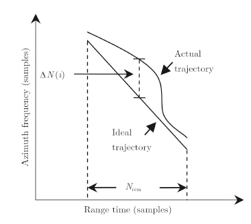
4.2 Cross-track velocity error compensationSince the motion of the moving target is not recorded by the system,the actual motion of the moving target should be estimated from the echo. According to the fourth exponential term of Eq. (4),the range walk trajectory of the moving target is affected by the cross-track velocity error. Based on existing processing results of simulations and real data,the range walk trajectory of the moving target with a constant cross-track velocity is a smooth rectilinear figure,whereas the range walk trajectory of the moving target with cross-track velocity error is an irregular curve. Therefore,we estimate the cross-track velocity error from the errors of the range walk trajectory. The principle of our cross-track velocity error estimation algorithm is shown in Fig. 3.
|
Fig.3 Principle of proposed motion error estimation algorithm |
According to the estimation of ${\bar f_{{\rm{dc}}}}$, the average cross-track velocity ${\bar{\! V \! _x }}$ can be calculated as
| ${\bar{\! \! \! V \! _x \!}} = \frac{{{{\bar f} \! _{{\rm{dc}}}}\lambda }}{2}$ | (10) |
Based on ${\bar{\! V \! _x }}$, an ideal moving target can be simulated,and the range walk trajectory of the ideal moving target can be used as a reference to extract the information of the cross-track velocity error. Calculate the azimuth shift △N between the ideal trajectory and the actual trajectory in each range cell. The length of △N is the number of the range walk migration cells Nrcm,which can be expressed as
| ${N_{{\rm{rcm}}}} = {\bar{\! \! \! V \! _x \!}}{T_{\rm{a}}}\frac{{2{f \! _s}}}{\rm{c}}$ | (11) |
| $\Delta {\hat f \! _{\rm{dc}}} = \frac{{{\rm{upsample}}(\Delta N,r)}}{{{N_\rm{a}}}}{\rm{PR}}{{\rm{F}}_{{\rm{ave}}}}$ | (12) |
where upsample(x,n) increases the sampling rate of x by inserting n-1 zero between samples,Na is the azimuth sample number,and r is the up-sampling rate,which is defined as
| $r = {N_{\rm{a}}}{\rm{/}}{N_{{\rm{rcm}}}}$ | (13) |
With Eq. (12),the cross-track velocity error can be obtained as
| $\Delta {\widehat{\! V \! _x}}({t_{\rm{a}}}) = \frac{{\Delta {{\hat f} \! _{{\rm{dc}}}} \cdot \lambda }}{2}$ | (14) |
The correction filter of the cross-track velocity error can be expressed as
| $H{{}_{Vx}}=\exp \left( -\text{j}\frac{4\pi }{\lambda }\Delta {{V}_{x}}({{t}_{\text{a}}}){{t}_{\text{a}}} \right)$ | (15) |
In this section,the whole moving target imaging strategy with the proposed algorithm is introduced. Based on the proposed non-ideal motion error compensation algorithm above,the imaging resolution of the moving target in real data condition can be significantly improved. The specific processing steps are as follows.
Step 1 Correct the non-ideal course of the platform with the INS data.
Step 2 Process the range compression and azimuth Fourier transform on the data,and indicate the moving targets in range-Doppler domain. In a single-antenna SAR system,the moving target can be indicated by the clutter filtering algorithm.
Step 3 Compensate for the platform velocity error with the INS data.
Step 4 Estimate and compensate for the cross-track velocity error of the moving target. With Eq. (14),the actual cross-track velocity of the moving target can be expressed as
| ${\widehat{\! V \! _x}}({t_{\rm{a}}}) = {\bar{\! V \! _x}} + \Delta {\widehat{\! V \! _x}}({t_{\rm{a}}})$ | (16) |
Step 5 Correct the range walk of the moving target with Eq. (16). Before the range walk correction,the range curve of the moving target[18, 19, 20] can be corrected by using
| ${{H}_{\text{RCMC}\_\text{C}}}=\exp \left( \text{j}\frac{2\pi {{V}_{\text{a}}}^{2}}{c{{R}_{0}}}{{f}_{\text{r}}}t_{\text{a}}^{2} \right)$ | (17) |
Step 6 Estimate the Doppler modulation rate of the moving target. The moving target can be focused by the Doppler modulation rate estimation.
Step 7 Utilize the PGA technique to further compensate for the residual high-order phase error.
Step 8 Relocate the focused image of the moving target to its actual location in the stationary SAR image.
5 Experimental ResultsIn this section,we simulate a typical airborne SAR system with following parameters (see Tab. 1) to validate the algorithm advanced above. A moving target,with the average cross-track velocity of 10 m/s,is located in the center of the scene,and the average velocity on the platform is 100 m/s. Three experiments are performed to validate the two sorts of motion errors,respectively.
| Tab. 1 Simulation parameters |
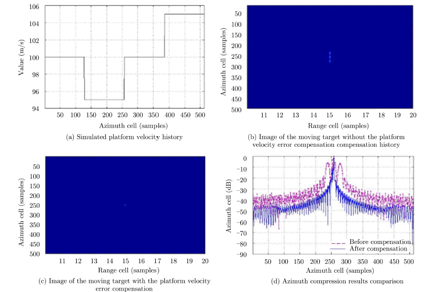
Firstly,we simulate the echo data with the platform velocity error. Assuming the platform velocity around 100 m/s,as shown in Fig. 4(a),the imaging results of the moving target without and with the proposed motion error compensation algorithm are shown in Fig. 4(b) and Fig. 4(c),respectively. It notices that,the moving target seriously smear without the compensation, which proves that the platform velocity error deteriorates the focusing results of the moving target as analyzed in Section 3. The azimuth compression results are compared in Fig. 4(d). The broken line represents the azimuth compression result without the proposed algorithm,we find that the energy of the target is compressed into three peaks,corresponding to the platform velocity 95 m/s,100 m/s,and 105 m/s. On the contrary,with the proposed algorithm,the moving target is focused into its ideal Doppler centroid,as represented by the solid line.
|
Fig.4 Simulation of the platform velocity error |
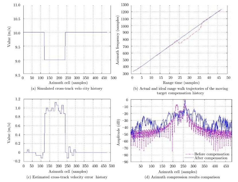
Secondly,the moving target with the cross-track velocity error is simulated. As shown in Fig. 5(a),the cross-track velocity of the moving target is set to change from 9 m/s to 10 m/s. Fig. 5(b) shows the actual and ideal range walk trajectories of the moving target,and it is validated that the range walk trajectory has a corresponding relationship with the cross-track velocity error. The cross-track velocity error estimated by the proposed algorithm is shown in Fig. 5(c). After compensation,the cross-track velocity of the moving target is about 10 m/s,therefore the estimation accuracy of the proposed algorithm is confirmed. Fig. 5(d) compares the azimuth compression results of the moving target with and without the proposed algorithm. According to the broken line,the energy of the moving target is spread on two Doppler centroids as a result of the cross-track velocity error,and the solid line shows that the Doppler centroid error is compensated through the proposed algorithm.
|
Fig.5 Simulation of the cross-track velocity error |
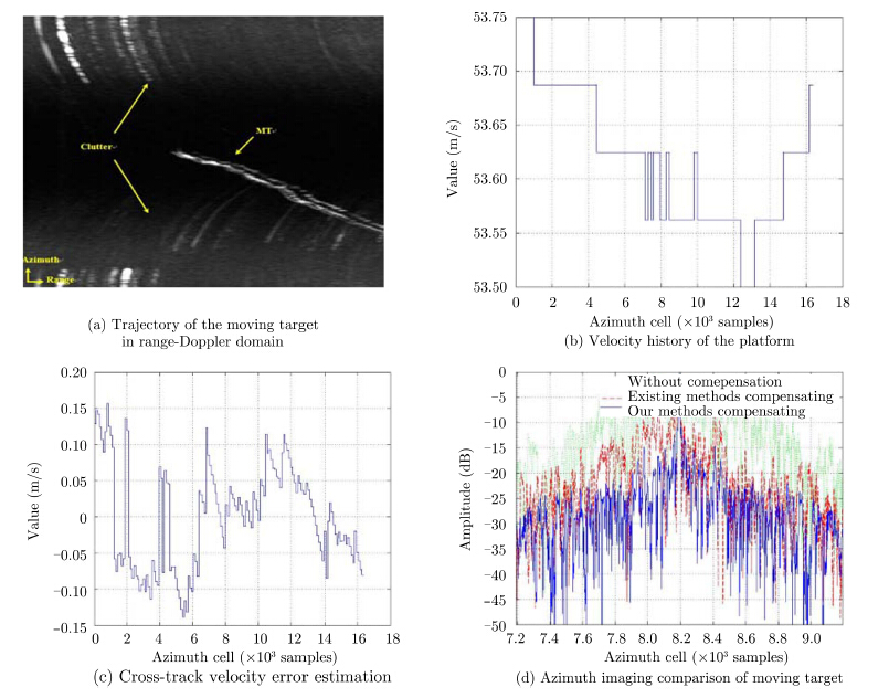
At last,the real X-band airborne SAR data is used to testify the effectiveness of motion error compensation in real applications. One moving target with complicated motions is found in the scene. The real data contains motion error while the data is acquired. Therefore,the imaging of moving target will be smeared without motion error compensation[21, 22].
The trajectory of the moving target in range-Doppler domain is shown in Fig. 6(a). It can be seen that the trajectory is not smooth. According to the analysis in Section 3,the imperfect curve results from the inconstant cross-track velocity of the moving target. The platform velocity history obtained from the INS data is shown in Fig. 6(b). The cross-track velocity error estimated by the proposed algorithm is shown in Fig. 6(c). According to Fig. 6(d),the azimuth imaging resolution of the moving target is significantly improved after the motion error compensation with the proposed algorithm,compared with without compensation and compensation with the existing methods (see Subsection 4.1).
|
Fig.6 Imaging of moving target real data with motion error compensation |
From the simulations and real data processing results,the validity of the proposed algorithm is finally confirmed.
6 ConclusionIn this paper,we establish a practical model of moving target with considering non-ideal motion errors. Based on this model,the impacts of two sorts of motion errors,the platform velocity error and the cross-track velocity error of the moving target,are analyzed,and a novel motion error compensation algorithm is proposed. Moreover,a moving target imaging strategy with the proposed algorithm is illustrated and the imaging resolution of the moving target in practical applications can be improved. Results of simulation and real data experiments have been employed to verify the effectiveness of the proposed algorithm.
| [1] | Barbarossa S. Detection and imaging of moving objects with synthetic aperture radar Part 1: Optimal detection and parameter estimation theory[J]. IEEE Proceedings-F Radar and Signal Processing, 1992, 139(1): 79-88.( 1) 1) |
| [2] | Jao J K. Theory of synthetic aperture radar imaging of a moving target[J]. IEEE Transactions on Geoscience and Remote Sensing, 2001, 39(9): 1984-1992.( 1) 1) |
| [3] | Tang L, Li D, Wu Y, et al.. Imaging of ground moving targets based on airborne SAR[J]. Journal of Systems Engineering and Electronics, 2005, 27(1): 1681-1684.( 1) 1) |
| [4] | Zhu S, Liao G, Qu Y, et al.. Ground moving targets imaging algorithm for synthetic aperture radar[J]. IEEE Transactions on Geoscience and Remote Sensing, 2011, 49(1): 462-477.( 1) 1) |
| [5] | Li Y, Wang Y, and Liu C. Detect and autofocus the moving target by its range walk in time domain[C]. 2011 International Conference on Wireless Communications and Signal Processing (WCSP), Nanjing, China, 2011: 1-5.( 1) 1) |
| [6] | Xing M, Jiang X, Wu R, et al.. [6] Motion compensation for UAV SAR based on raw radar data[J]. IEEE Transactions on Geoscience and Remote Sensing, 2009, 47(8): 2870-2883.( 1) 1) |
| [7] | Wang R, Luo Yun-hua, Deng Yun-kai, et al.. Motion compensation for high resolution automobile FMCW SAR[J]. IEEE Geoscience and Remote Sensing Letters, 2013, 10(5): 1157-1161.( 1) 1) |
| [8] | Sun G C, Xing M D, Xia X G, et al.. Robust ground moving target imaging using Deramp-keystone processing[J]. IEEE Transactions on Geoscience and Remote Sensing, 2013, 51(2): 966-982.( 1) 1) |
| [9] | Zhang S X, Xing M D, Xia X G, et al.. A novel moving target imaging algorithm for HRWS SAR based on local maximum- likelihood minimum entropy[J]. IEEE Transactions on Geoscience and Remote Sensing, 2014, 52(9): 5333-5348.( 1) 1) |
| [10] | Soumekh M. Synthetic Aperture Radar Signal Processing with MATLAB Algorithms[M]. New York, USA: Wiley- Hall, Inc., 1999: 186-230.( 1) 1) |
| [11] | Li Y, Liu C, Wang Y, et al.. A robust motion error estimation method based on raw SAR data[J]. IEEE Transactions on Geoscience and Remote Sensing, 2012, 50(7): 2780-2790.( 1) 1) |
| [12] | Zhang Z. Introduction of Airborne and Spaceborne Synthetic Aperture Radar[M]. Beijing: Publishing House of Electronics Industry, 2004: 27-28.( 1) 1) |
| [13] | Yang J, Liu C, and Wang Y F. Detection and imaging of ground moving targets with real SAR data[J]. IEEE Transactions on Geoscience and Remote Sensing, 2015, 53(2): 920-923.( 1) 1) |
| [14] | Yang J, Liu C, and Wang Y F. Imaging and parameter estimation of fast-moving targets with single-antenna SAR[J]. IEEE Geoscience and Remote Sensing Letters, 2014, 11(2): 529-533.( 1) 1) |
| [15] | Luo Y H, Song H J, Robert Wang, et al.. An accurate and efficient extended scene simulator for FMCW SAR with static and moving targets[J]. IEEE Geoscience and Remote Sensing Letters, 2014, 11(10): 1672-1676.( 1) 1) |
| [16] | Lü G H, Wang J F, and Liu X Z. Ground moving target indication in SAR images by symmetric defocusing[J]. IEEE Geoscience and Remote Sensing Letters, 2013, 10(2): 241-245.( 1) 1) |
| [17] | Li F K, Held D N, et al.. Doppler parameter estimation for spaceborne synthetic-aperture radars[J]. IEEE Transactions on Geoscience and Remote Sensing, 1985, 23(1): 47-56.( 1) 1) |
| [18] | Yang J G, Huang X T, Jin T, et al.. New approach for SAR imaging of ground moving targets based on a keystone transform[J]. IEEE Geoscience and Remote Sensing Letters, 2011, 8(4): 829-833.( 1) 1) |
| [19] | Liu B, Yin K, Li Y, et al.. An improvement in multichannel SAR-GMTI detection in heterogeneous environments[J].IEEE Transactions on Geoscience and Remote Sensing, 2015, 53(2): 810-827.( 1) 1) |
| [20] | Li Y K, Wang T, Liu B C, et al.. High-resolution SAR imaging of ground moving targets based on the equivalent range equation[J]. IEEE Geoscience and Remote Sensing Letters, 2015, 12(2): 324-328.( 1) 1) |
| [21] | Cho B L, Kong Y K, Park H G, et al.. Automobile-based SAR/InSAR system for ground experiments[J]. IEEE Geoscience and Remote Sensing Letters, 2006, 3(3): 401-405.( 1) 1) |
| [22] | Fornaro G, Franceschetti G, and Perna S. Trajectory deviations in airborne SAR: Analysis and compensation[J]. IEEE Transactions on Aerospace and Electronic Systems, 1999, 35(7): 997-1009.( 1) 1) |


